Control device, in particular in the form of an electric switch for electric handtools

a control device and electric switch technology, applied in the direction of electrical apparatus construction details, portable power-driven tools, lighting and heating apparatus, etc., can solve the problems of insufficient heat dissipation, component generation of power loss, and other parts of the circuit arrangement can likewise generate heat loss, so as to improve heat dissipation and improve heat dissipation. , the effect of improving the heat dissipation rang

Active Publication Date: 2009-08-27
MARQUARDT GMBH SCHLOSSTRASSE 16 7201 RIETHEIM-WEILHEIM 1 WEST GERMANY
View PDF10 Cites 7 Cited by
  • Summary
  • Abstract
  • Description
  • Claims
  • Application Information

AI Technical Summary

Benefits of technology

[0014]The advantages achieved by the invention are, in particular, that the improved heat dissipation allows for the use of new, higher power ranges. Furthermore, this is a passive cooling system so that no energy is required for operation of the means for cooling, and this is particularly advantageous for use in rechargeable-battery-powered tools. Finally, it is also possible to use physically smaller electronic components and power semiconductors with lower specifications, and this leads to cost savings. Furthermore, it is possible to dispense with the expensive heat sinks which are required for present-day switches. The invention advantageously provides a direct-current (DC) high-power switch for use in handheld electrical tools in the upper power range, which is particularly suitable for electrical tools which operate using lithium-ion rechargeable batteries.

Problems solved by technology

By virtue of its function as a power component, the component generates a power loss in the form of heat, which must be dissipated from the housing.
Other parts of the circuit arrangement can likewise generate heat losses.
It has now been found that, in some cases, the heat dissipation which can be achieved in this way is not sufficient.
It is obvious that, in situations such as this, the operational reliability of the switch and therefore of the electrical tool as well suffers.

Method used


Image

  • Control device, in particular in the form of an electric switch for electric handtools
  • Control device, in particular in the form of an electric switch for electric handtools

Examples


Embodiment Construction

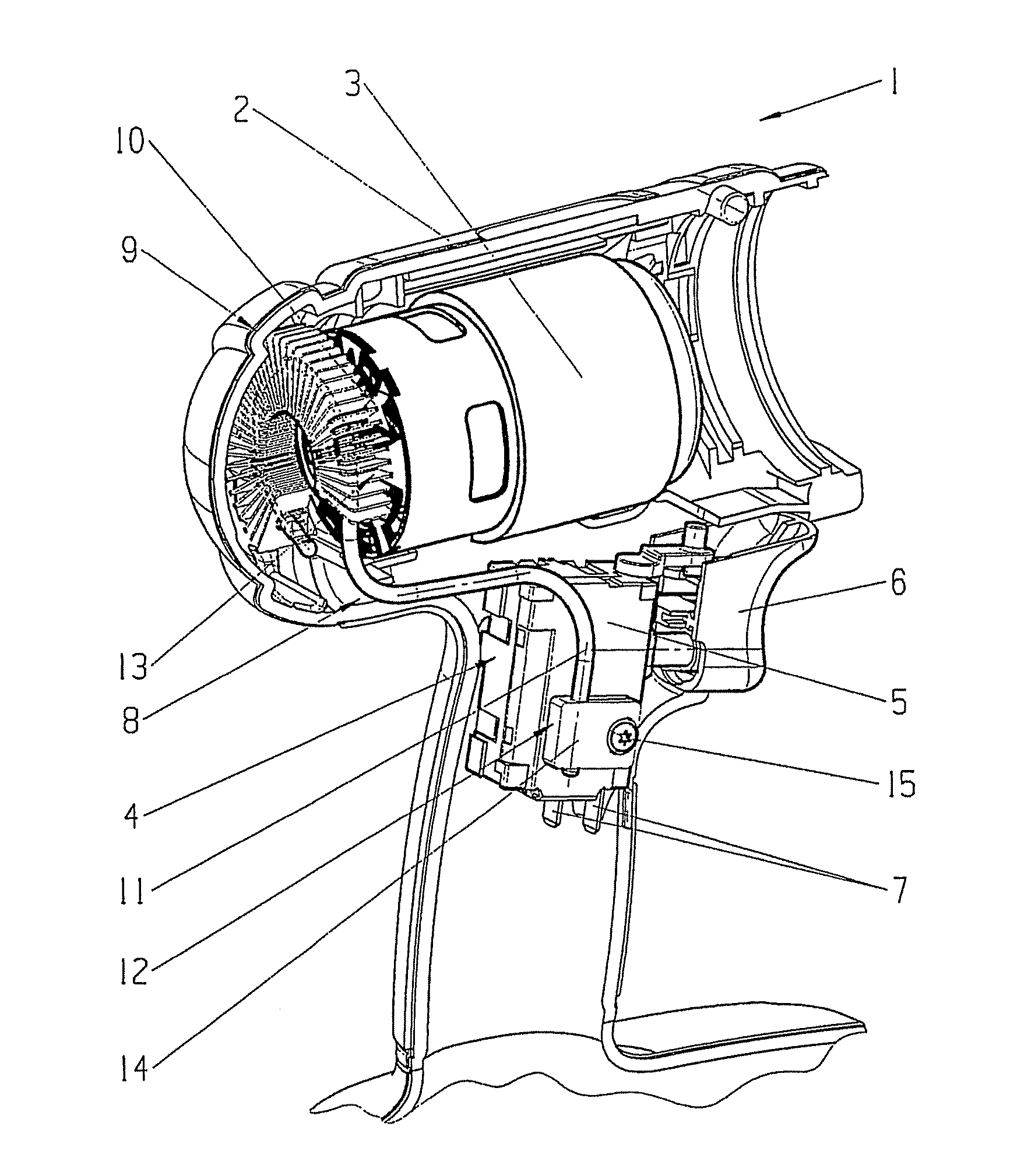
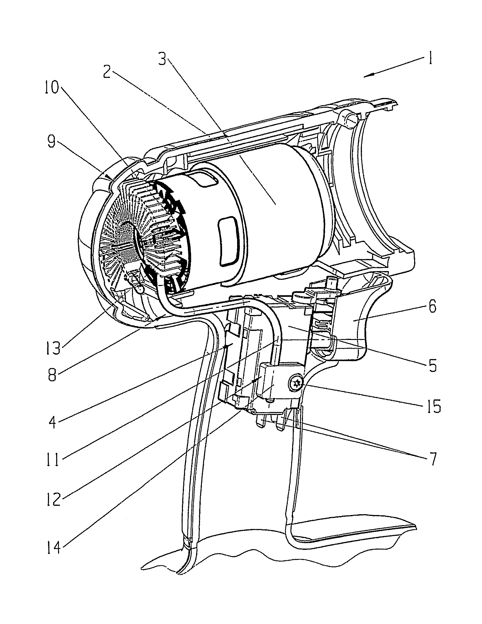
[0017]The FIGURE shows a housing half-shell 2 for an electrical tool 1 in a manner in which the electric motor 3, which is located in the electrical tool housing of the electrical tool 1, can be seen together with the fan impeller 10, which generates the cooling air flow for the electric motor 3, and the electrical switch 4. The electrical tool 1 may be a rechargeable-battery and / or plug-powered electrical tool, for example a drilling machine, a grinder, a saw, a plane, an angle grinder or the like.

[0018]The switch 4 has a housing 5 which is used to hold a contact system, which comprises a known moving switching contact as well as a known stationary contact, both of which are not shown in the figure. The housing 4 is held in the housing half-shell 2 such that an operating member 6, which is arranged on the housing 5 and can be moved manually by the user, projects out of the handle on the housing half shell 2. The operating member 6 acts on the switching contact to switch the contact...


PUM


Abstract

A control device, in particular an electrical switch for use for an electrical tool such as a rechargeable-battery and/or plug-powered electrical tool having an electric motor. The switch has a housing for holding at least one heat-generating component such as a power transistor, a MOSFET, a triac or the like, which is arranged in particular in an electrical circuit arrangement which, for example, is used for open-loop and/or closed-loop control of the electric motor by appropriate open-loop and/or closed-loop control of the electrical load current flowing through the component to the electric motor. A means for thermal conduction is connected on the one hand to the housing of the electrical switch, and/or to the heat-generating component, in particular to the power semiconductor which is located in the housing, and on the other hand to a cooled area which is associated with the switch.

Description

CROSS REFERENCE TO RELATED APPLICATIONS [0001]This application is a continuation of International Application No. PCT / DE2007 / 001408, filed Aug. 9, 2007, which designated the United States, and claims the benefit under 35 USC §119(a)-(d) of German Application No. 10 2006 037 446.0 filed Aug. 10, 2006, the entireties of which are incorporated herein by reference.FIELD OF THE INVENTION [0002]The invention relates to a control device, particularly a control device used as an electrical switch for an electrical tool.BACKGROUND OF THE INVENTION [0003]Control devices such as these are used in particular as electrical switches for an electrical handtool having an electric motor, such as a rechargeable-battery and / or plug-powered electrical tool. These electrical tools may be drilling machines, grinders, saws, planes, angle grinders or the like.SUMMARY OF THE INVENTION [0004]DE 195 08 925 A1 discloses an electrical switch for an electrical tool, which has a housing for holding an electrical ...

Claims


Application Information

Patent Timeline
Patent Type & Authority Applications(United States)
IPC IPC(8): H05K7/20
CPCB25F5/008H01H2009/523H01H9/52H01H9/06
Inventor ERB, TINOPFEIFFER, DIRKFIEDERER, KLAUS
Owner MARQUARDT GMBH SCHLOSSTRASSE 16 7201 RIETHEIM-WEILHEIM 1 WEST GERMANY
Why Eureka
Try Eureka