
Thermalization of gaseous precursors in CVD reactors

a gaseous precursor and cvd technology, applied in the direction of chemically reactive gases, crystal growth process, coatings, etc., can solve the problems of inability to rapidly react, large fractions of inadequately thermalized precursor gases can be simply wasted, and the waste of inadequately thermalized precursors can be greater, so as to improve the efficiency of the intended growth reaction, improve the thermalization of process gases, and reduce the efficiency of unintended reactions

Inactive Publication Date: 2009-08-27
S O I TEC SILICON ON INSULATOR THECHNOLOGIES
View PDF19 Cites 50 Cited by
  • Summary
  • Abstract
  • Description
  • Claims
  • Application Information

AI Technical Summary

Benefits of technology

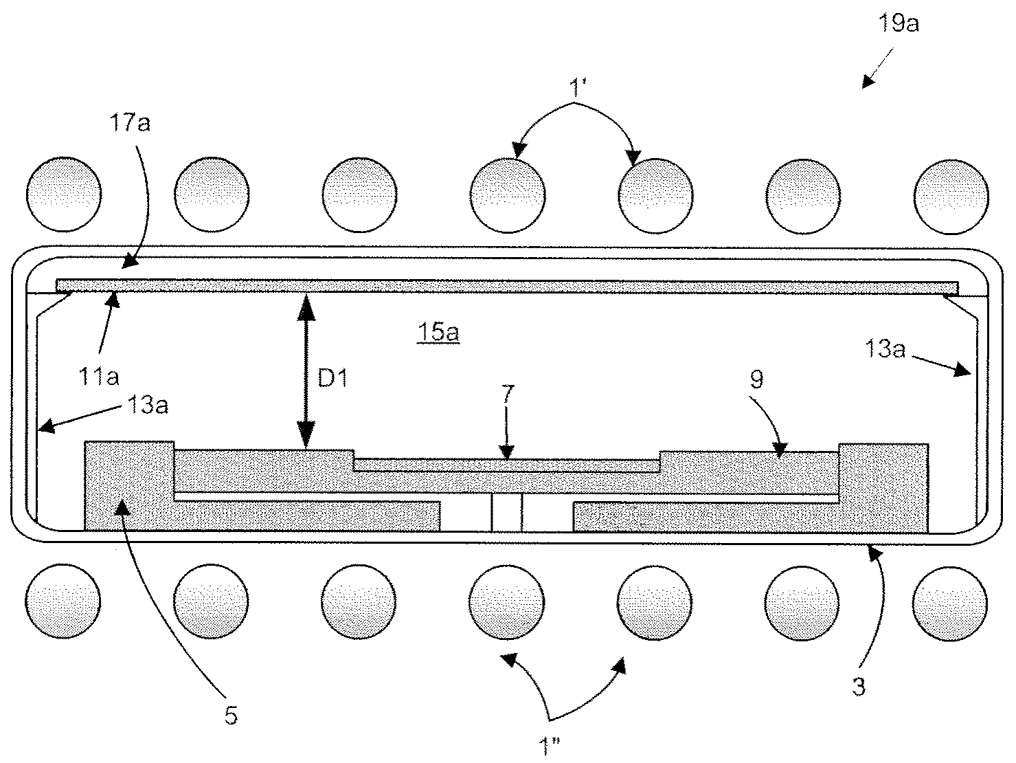
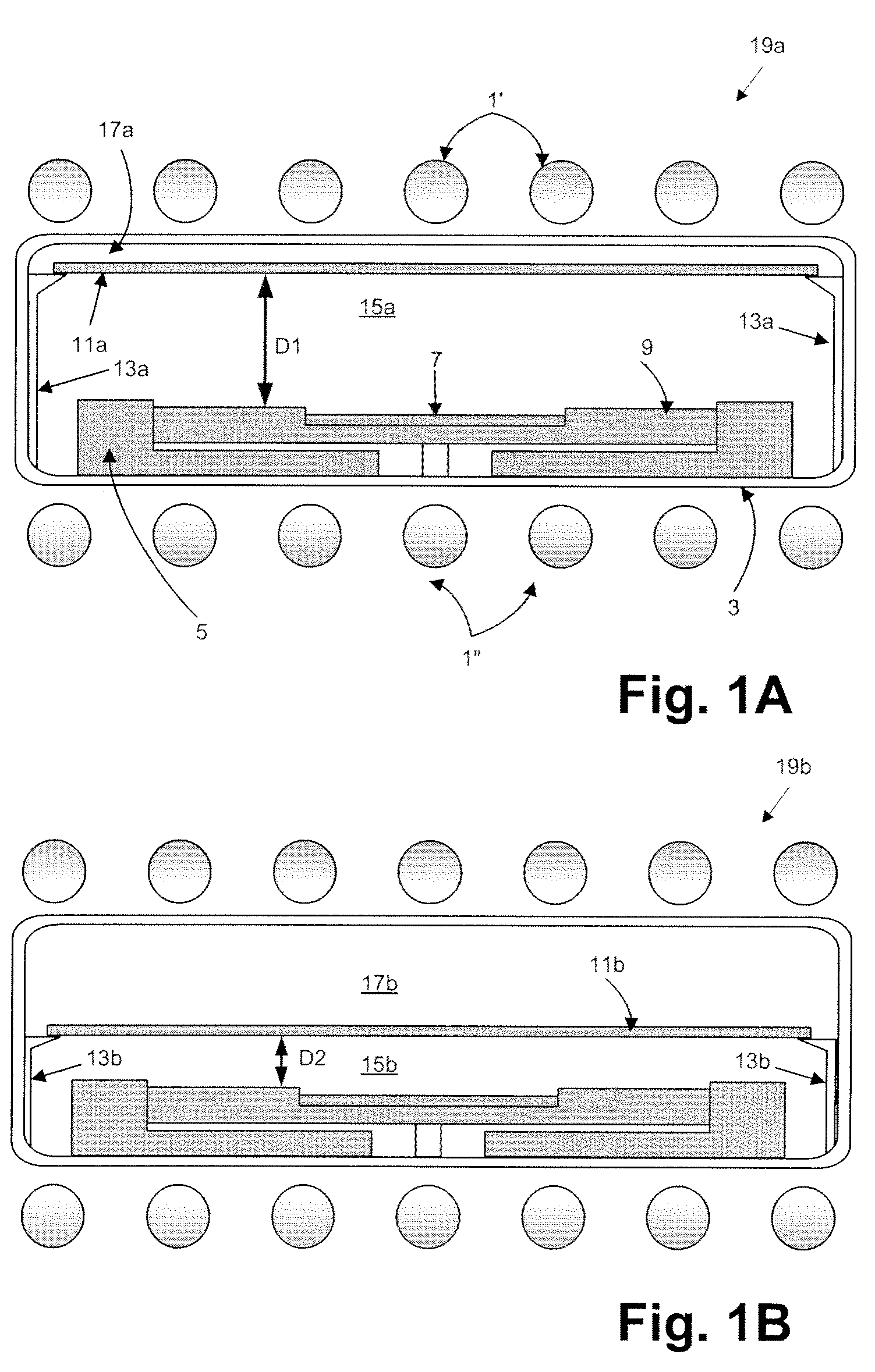
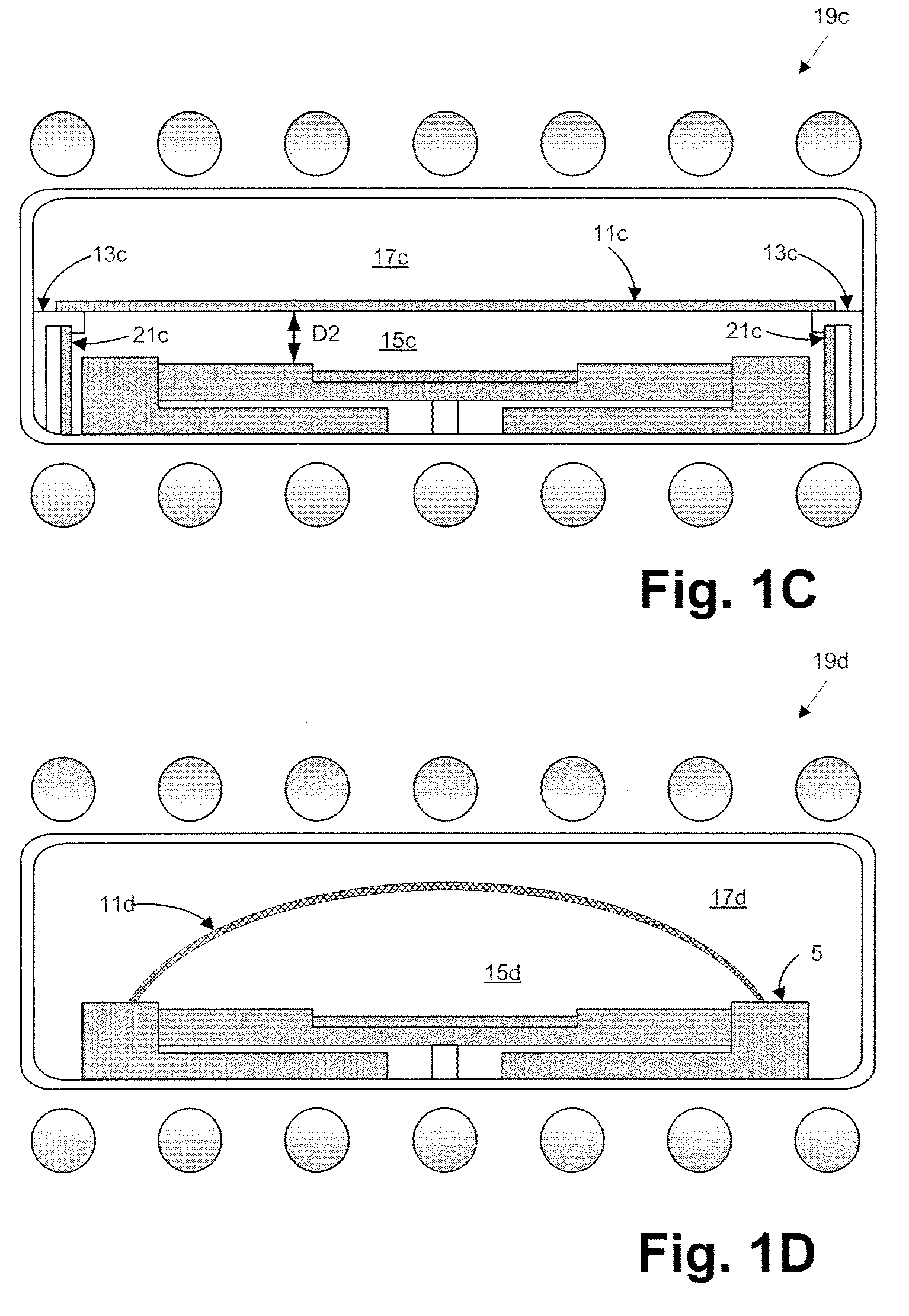
[0011]Increased heat transfer promotes improved precursor gas thermalization prior to and at the time of reaction, thereby increasing the efficiency of intended reactions between the precursor gases while limiting unwanted reactions that can lead to unreactive complexes or species. If such complexes or species do form, improved thermalization can promote their decomposition back into precursor forms. Consequently, this invention provides more rapid growth of semiconductor material, improves the efficiency of precursor usage, and limits incorporation of unwanted complexes or species into the growing epilayer. Secondary advantages can include reduction or limitation of unwanted deposition of the semiconductor material, e.g., on reactor chamber wall, or of unwanted condensation of reaction precursors or reaction by-products.
[0022]In further preferred embodiments, the inner zone can have two, three, or four sides which can be planar or curvilinear. A single boundary is not preferred. In further embodiments, two or more boundaries of the inner zone can be heated, e.g., by exposure to radiation from heating lamps. It is not preferred for only a single boundary of the inner zone to be heated. In CVD systems provided with automatic or robotic means for substrate transfer in and out of a reactor chamber, the inner zone is preferably sized and configured so that the automatic or robotic means can transfer substrates without interference.
[0023]In further preferred embodiments, the heat transfer structures can be modularly constructed so that different numbers of heat transfer structures, e.g., heat transfer plates, of differing sizes and configurations can be used from time-to-time in a single reactor in order to accommodate the needs of different CVD processes. For example, heat transfer structures can be provided at different locations to heat a local area, or can be arranged to distribute heat also to the quartz reactor wall to prevent, e.g., deposition or condensation. Also, heat transfer structures can be combined with non-absorbent materials (e.g., IR transparent quartz) in various shapes and arranged in locations where heating is not desirable. Thereby, heat can be distributed to selected locations in the inner zone and not to other locations in the inner zone whilst the boundary of the inner zone can remain continuous to avoid introduction of unwanted gas turbulence.
[0033]Thus, the heat transfer structures of this invention provide improved process gas thermalization leading to improved efficiency of the intended growth reaction, reduced efficiency of unintended reactions, reduced adduct formation, reduced incorporation of unwanted complexes or species into the growing epilayer, and the like. Further, these structures at least partially limit unwanted deposition on the outer reactor at lower temperatures (cold walls) by preventing thermalized precursor gases from contacting these walls. Reactor cleanliness and lifetime are thereby improved.

Problems solved by technology

However, this direct reaction proceeds efficiently only if the precursor gases are at temperatures of about 900-930° C. and above, because at lower temperatures (it is believed) the precursor gases have not adequately decomposed into directly reactive species and thus cannot rapidly react.
Accordingly, significant fractions of inadequately thermalized precursor gases can be simply wasted; they pass through the reactor and out the exhaust either unreacted or as unreactive adducts.
Further, waste of inadequately thermalized precursors can be greater in high volume manufacturing (HVM) of III-V compounds, and the wasted fraction can increase as higher growth rates are sought.
This is possibly because: higher growth rates require higher precursor flow rates; higher flow rates decrease times available for reaction in the vicinity of the intended substrate; and decreased reaction times reduce the efficiency of reaction-rate-limited growth processes.
However, problems have hindered achieving adequate thermalization of precursor gases, especially in the case of HVM of III-V compounds where corrosive precursor gases must be thermalized to high temperatures.
First, it has not been possible to adequately thermalize precursor gases prior to entering the reactor chamber.
Typical precursor gases at high temperatures can rapidly corrode materials commonly used in known gaseous delivery systems, and such corrosion can further lead to particle formation / deposition in delivery lines, reduced reactor cleanliness, eventual line blockage, and so forth.
But use of corrosion-resistant materials, e.g., quartz, graphite, silicon carbide, etc, in gaseous delivery systems would be prohibitively expensive.
Further, it has also not been possible to achieve adequate precursor-gas thermalization within known CVD reactors after their entry into the reactor chamber.
At such high flow rates, precursor gases move too quickly through the high temperature zone in the reactor to become adequately thermalized prior to traversing the growth substrate.

Method used


Image

  • Thermalization of gaseous precursors in CVD reactors
  • Thermalization of gaseous precursors in CVD reactors
  • Thermalization of gaseous precursors in CVD reactors

Examples


Embodiment Construction

[0038]In the following, the invention is described largely in terms of preferred embodiments useful in cold-wall CVD reactors heated with radiant heating elements, e.g., IR heating lamps, and having walls substantially transparent to radiated energy, e.g., comprising quartz. It should be understood that these preferred embodiments are not limiting, and as described above, this invention is useful on other types of CVD reactors with other types of heat sources. Provided first is a general description of such embodiments, which is followed by descriptions of exemplary embodiments illustrating particular features of the invention.

[0039]The term “substantially” as used throughout this application is to be understood as referring to relevant standard manufacturing tolerances and to other relevant commercially-reasonable standards. For example, a “substantially” planar surface of B4C is a surface that is planar within standard manufacturing tolerances, the tolerances being adequate to ins...


PUM

PropertyMeasurementUnit
temperatureaaaaaaaaaa
temperaturesaaaaaaaaaa
melting pointaaaaaaaaaa

Abstract

The present invention relates to the field of semiconductor processing and provides apparatus and methods that improve chemical vapor deposition (CVD) of semiconductor materials by promoting more efficient thermalization of precursor gases prior to their reaction. In preferred embodiments, the invention comprises heat transfer structures and their arrangement within a CVD reactor so as to promote heat transfer to flowing process gases. In certain preferred embodiments applicable to CVD reactors transparent to radiation from heat lamps, the invention comprises radiation-absorbent surfaces placed to intercept radiation from the heat lamps and to transfer it to flowing process gases.

Description

CROSS-REFERENCE TO RELATED APPLICATIONS[0001]This application claims the benefit to U.S. Provisional Application No. 61 / 031,837 filed Feb. 27, 2008, which is included by reference herein in its entirety for all purposes.FIELD OF THE INVENTION[0002]The present invention relates to the field of semiconductor processing and provides apparatus and methods that improve chemical vapor deposition (CVD) of semiconductor materials by promoting more efficient thermalization of precursor gases prior to their reaction.BACKGROUND OF THE INVENTION[0003]The temperature of gaseous precursors prior to their reaction in a chemical vapor deposition (CVD) reactor is an important parameter for achieving efficient deposition at the desired location, e.g., for efficiently depositing the intended semiconductor material on the intended substrate.[0004]Consider, for example, growth of GaN by halide (hydride) vapor phase epitaxy (HVPE) processes. Certain HVPE processes react gaseous GaCl3 directly with gaseou...

Claims


Application Information

Patent Timeline
Patent Type & Authority Applications(United States)
IPC IPC(8): C23C16/44C23C16/54
CPCC23C16/303H01L21/0262C30B25/105C23C16/448
Inventor ARENA, CHANTALWERKHOVEN, CHRISTIAAN J.BERTRAM, JR., RONALD THOMASLINDOW, ED
Owner S O I TEC SILICON ON INSULATOR THECHNOLOGIES
Learn More