Buoyant blade free stream tidal power device

a technology of tidal power and buoyant blades, applied in the direction of electric generator control, couplings, fluid couplings, etc., can solve the problems of destroying native ecosystems, difficult to design a turbine to be efficient or even effective in such a variable environment, and difficult to efficiently extract power. , to achieve the effect of safe unloading

Inactive Publication Date: 2009-09-03
RINK PHILIP A
View PDF5 Cites 33 Cited by
  • Summary
  • Abstract
  • Description
  • Claims
  • Application Information

AI Technical Summary

Benefits of technology

[0010]Two forms of the invention are described. In either form, the new approach keeps the single blade turbine vertical in the current stream using the blade's own buoyancy. A hinge at the base allows the blade to deflect and “shrug off” kelp or other debris, eliminating the requirement for a huge foundation, mounting pole, or guy wires. The use of a freely mounted, buoyant blade also allows the blade to pivot and safely unload during extremely high currents, protecting the structure while still generating power.

Problems solved by technology

This makes the power difficult to extract efficiently.
In the process they modify the environment they utilize, often displacing or destroying native ecosystems.
It is very difficult to design a turbine to be efficient or even effective in such a variable environment.
In many areas water flows carry debris such as fishing nets and fishing lines, kelp fronds or stalks (which can be extremely tough and entangling), boat anchors and anchor lines, and deadheads and other floating wood.
This debris can not only clog or jam the mechanism of a water-windmill, but can build up on the structure or anchoring system significantly increasing the load on the foundation and requiring complicated intervention using divers or underwater vehicles to correct.
They rotate at fairly high speeds (relative to the marine environment and the animals that live there) with high tip velocities causing damage to either the turbine blade or the struck object in the event of a collision.
If the struck object is a small tree (deadhead), only monetary damage is sustained.
If the struck object is a whale or a school of migrating salmon, the carnage and subsequent adverse publicity could easily destroy the local tidal power industry.
If a free-stream tidal plant were to cause significant ecological damage, even perceived damage, it would be subject to eco-terrorism and “monkey-wrenching”.
Water-windmills would be extremely easy to damage or destroy.
Buoy-hung chains launched elsewhere that follow the current into the turbine area will become entangled, requiring difficult servicing or equipment replacement.

Method used


Image

  • Buoyant blade free stream tidal power device
  • Buoyant blade free stream tidal power device
  • Buoyant blade free stream tidal power device

Examples


embodiment 1

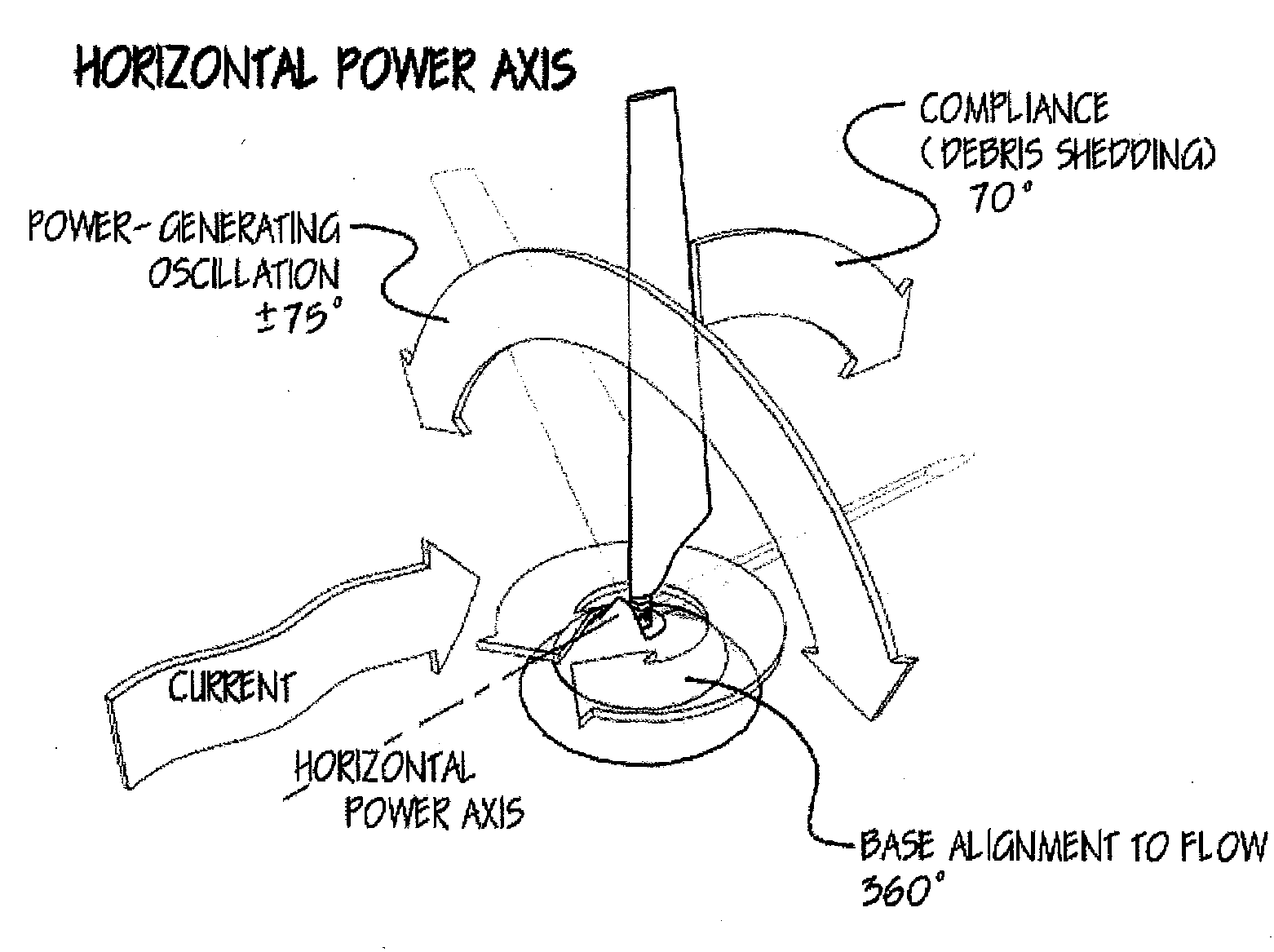
Horizontal Power Axis Parallel to Flow Stream

[0021]In its first form, shown in FIG. 1, the new system is a single blade or wing that projects upward from a base or foundation on or in the sea floor. The blade is oriented to the prevailing current flow, and its pitch is controlled to make the blade swing to and fro across the current. Power is extracted by resisting the torque created by the blade where it attaches to the base.

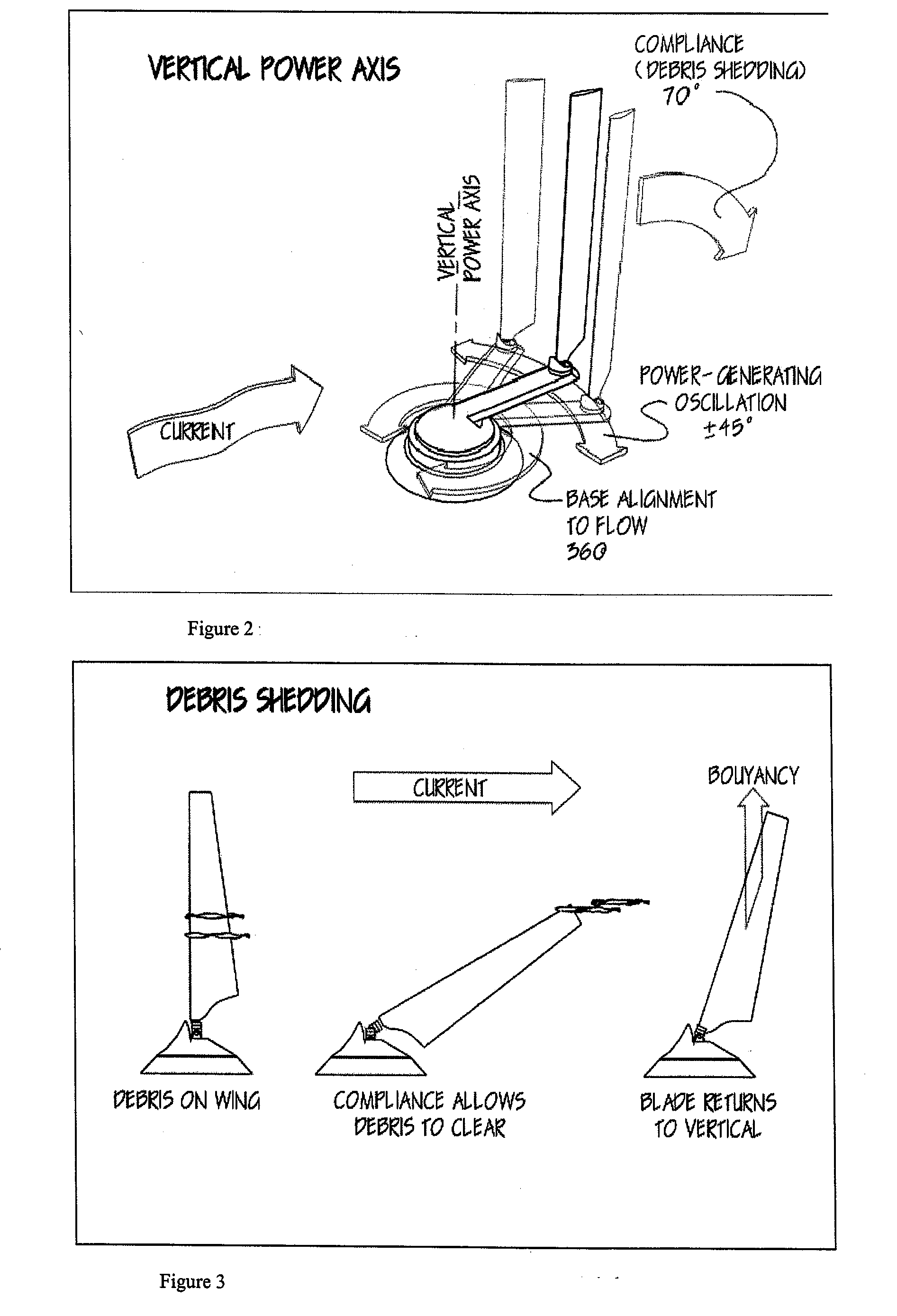
[0022]A key feature of the new system is that the blade is buoyant and is mounted compliantly in the current-flow axis. Kelp or debris that entangles the blade will increase drag on the blade, causing it to lean back until the debris clears itself (FIG. 3). The blade will also lean back in very high-current events, unloading the blade and preventing structural damage. In addition, the loads on the system's base or foundation are greatly reduced since buoyancy keeps the blade in the current stream, not a force imposed through the foundation. Variable-buoyancy c...

embodiment 2

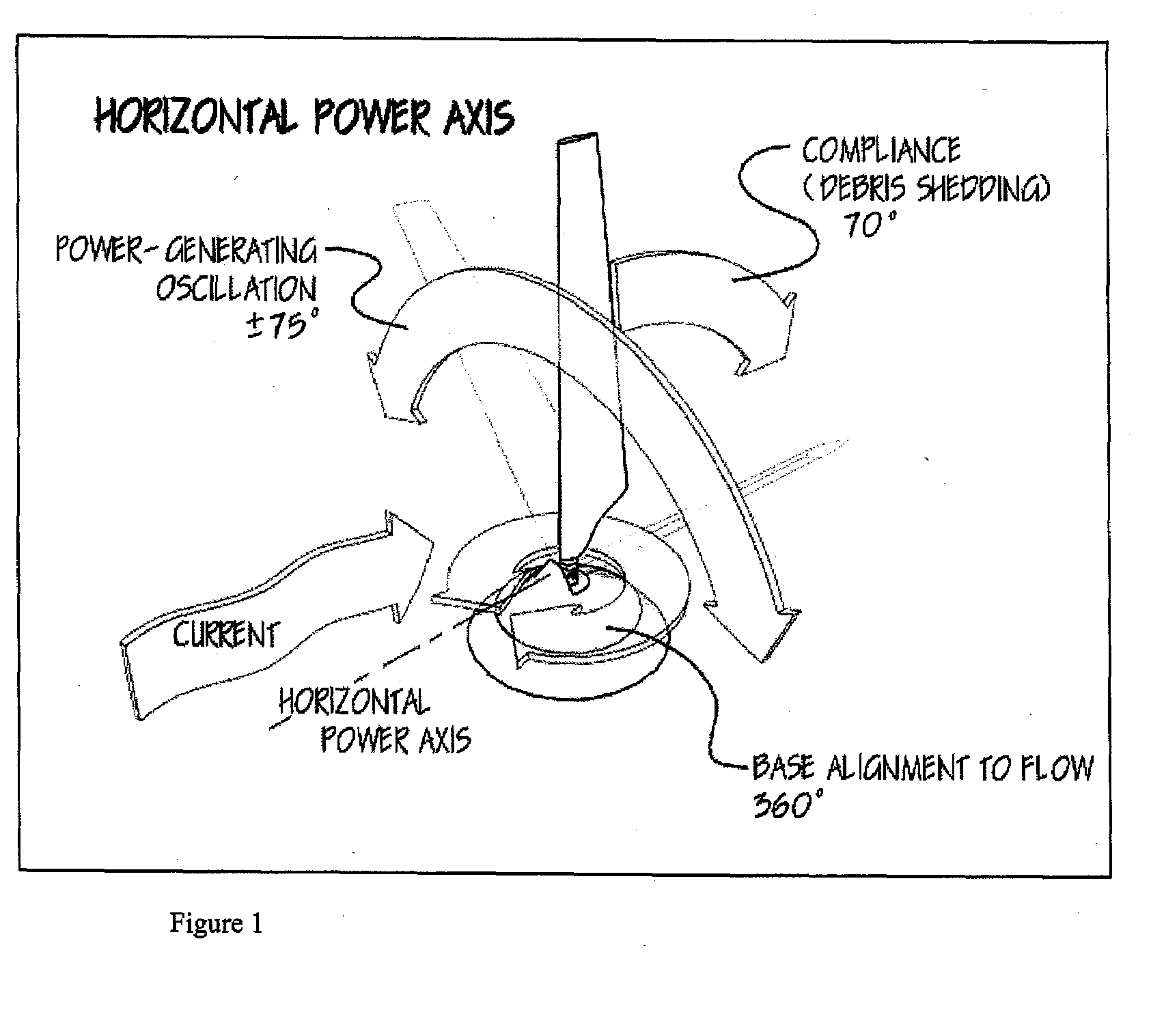
Vertical Power Axis at Right Angles to Flow Stream

[0027]Placing the power axis vertically, normal to the current flow, and having the vertical blade oscillate in an arc behind and around the power axis creates interesting opportunities worth investigating (FIG. 2). The blade will still shed debris and excess load though the same buoyancy / passive hinge approach, but the blade can now be constant cross section. The angle of attack is constant, so provisions are not required to twist the blade. The anchor / base needs to be tall enough to get most of the blade out of the seafloor boundary layer, but the loads on the base will be limited to reacting the torque and keeping the entire system from washing downstream. The blade will keep itself vertical using its buoyancy. The orientation axis will now be either the same as or parallel to the power axis. The arm will sweep through approximately 90-110 degrees.

[0028]This configuration is similar to the BioPower Systems bioSTREAM approach, but...


PUM


Abstract

Accordingly, the system for extracting power from tidal or other water action in a water region having a bottom surface, comprises: a base assembly positionable on the bottom surface of the water region; a buoyant blade assembly mounted on the base assembly, the blade assembly including at least one buoyant blade member, wherein the blade assembly or the blade member is capable of oscillating through an angle, wherein the buoyant blade member is mounted such that when the base assembly is positioned properly in the water region relative to the direction of the tide or other water action, torque is generated by the oscillating movement of the buoyant blade assembly or the buoyant blade member, and wherein the base assembly includes a power-extracting mechanism responsive to the torque generated by the tide or other action of water or the buoyant blade assembly; and a system for coupling the torque to the power-extracting mechanism.

Description

TECHNICAL FIELD [0001]This invention relates to the field of extracting power from moving streams of water. These moving streams of water are typically either tidal flows resulting from landmasses acting on the rise and fall of the tides, or riverine flows resulting from water flowing downstream.BACKGROUND OF THE INVENTION [0002]As seawater sloshes in and out of inlets under the influence of the moon's gravitational pull, currents are created. These water currents contain substantial amounts of kinetic energy that can be harvested at predictable times to provide power, usually in the form of electricity. River flows are also potential sources of “tidal” power.[0003]Tidal or riverine currents are often low-density power sources, flowing at 3-5 knots or less. This makes the power difficult to extract efficiently. Hydroelectric dams and their coastal cousins the barrage plants amplify the energy density of the water and then harvest the energy using high-pressure, high-velocity turbine...

Claims


Application Information

Patent Timeline
Patent Type & Authority Applications(United States)
IPC IPC(8): F03B13/10
CPCF03B13/264Y02E10/28F03B17/06Y02E10/30Y02E10/20
Inventor RINK, PHILIP A.
Owner RINK PHILIP A
Why Eureka
Try Eureka