A motor for a blower or a fan for an
HVAC, or a pump has a significant amount of
electric power consumption, which may range from several times to several ten times the amount used in different fields such as, e.g., the field of industrial
mechanical devices or
machine tools, etc., due in part because such a motor is required to be operated continuously for typically at least several hours or more per day.
Particularly, the
electric power consumption required for driving a blower or a fan for an HVAC, or a pump takes a very large portion in a BLM.
Further, the use of a BLM affects directly the efficiency and performance of a driving
system for an HVAC or a pump.
However, there is a problem that causes an unnecessary over-speed operation and hence a significant loss of
electric power because this AC
induction motor is difficult to control.
For example, it is difficult to control a speed necessarily required for providing an energy saving and convenient operation conditions.
However, the use of a separate
inverter causes a
noise problem, and has a certain limit in providing a program suitable for various required operation conditions, in addition to a speed controlling, due to a low operation efficiency in terms of economic efficiency (an
energy consumption amount compared to costs).
However, the motors for driving a fan using an ECM are designed to be used mainly as motors for driving simply a compact or low-capacity fan with 100 Watts or less, and thus have a limit in that they are not suitable for an HVAC designed for the use of a high-capacity housing or industrial purpose.
Further, in the
control system and methods for the multi-parameter electronically commutated motor disclosed in the '058 Patent, since a
microprocessor controls an ECM depending on parameter signals pre-stored in the programmable memory, it is impossible to respond properly in real time when, for example, an abnormal operation condition may occur.
However, in case of sensing a position of a rotor using this sensor-less manner, there are problems that an unstable transient phenomenon may occur at a startup of the ECM and a high possibility of a mal-operation may occur due to a
vulnerability to an
electromagnetic noise.
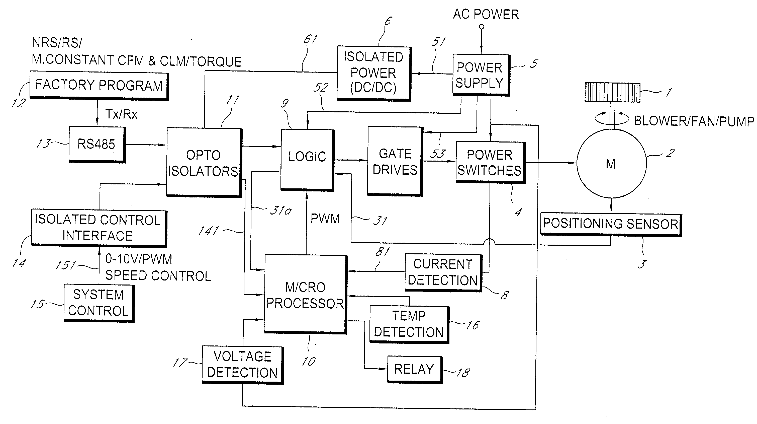
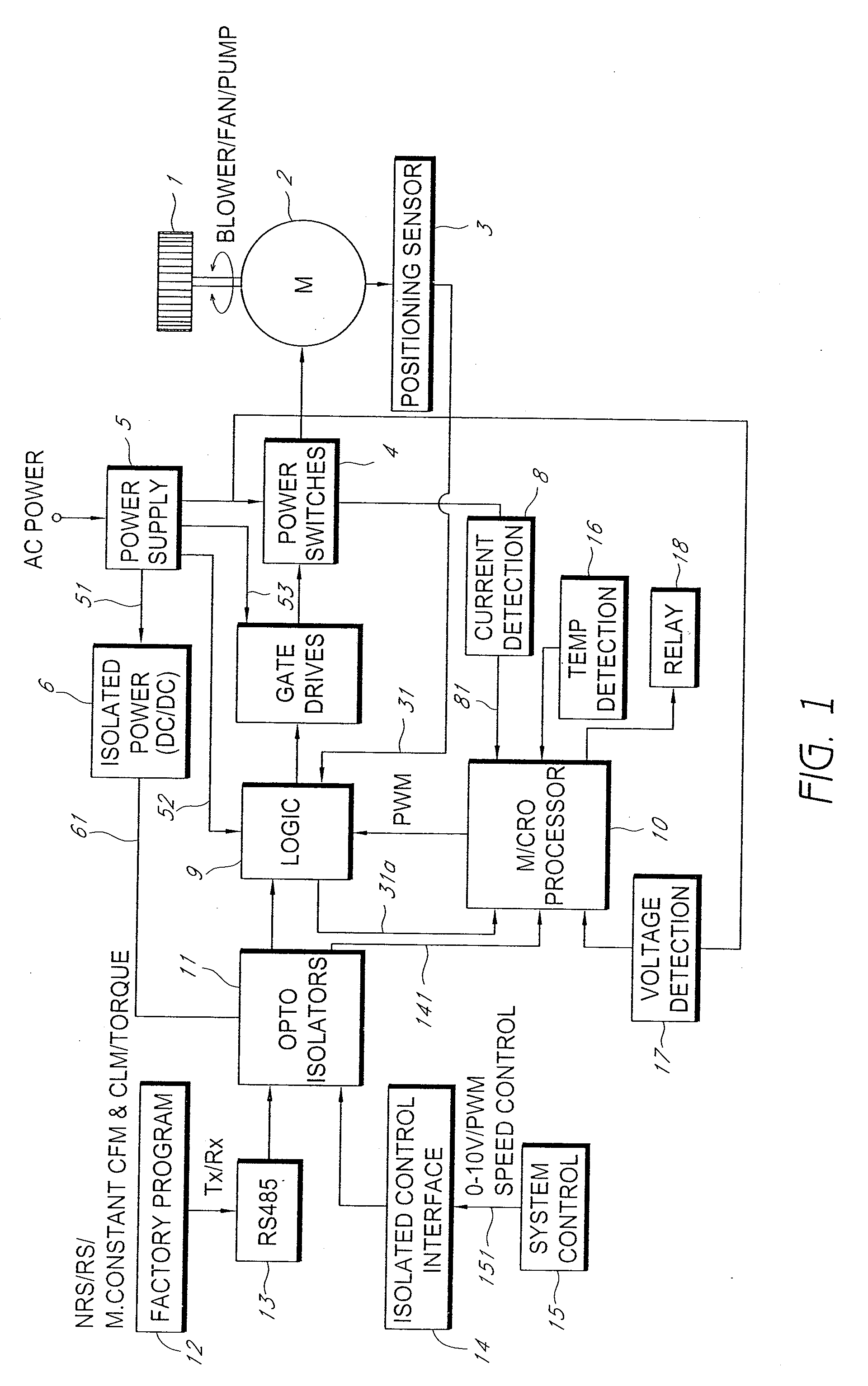
In the meanwhile, conventional control systems of a motor do not have means capable of controlling efficiently a
system for driving various kinds of blowers or fans for an HVAC, or a pump, such as means or functions including a non-regulated speed control (NRS) operation function, a regulated speed control (RS) operation function, a
constant torque control function, a constant air flow / constant liquid flow
control function, a
remote communication and monitoring function, a
network control means or function capable of controlling a drive of multiple fans or pumps using a mod
bus, and a data
logging means or function capable of checking operation states or records of a
control system for an HVAC or a pump.
Moreover, conventional control systems of a motor have a problem in that they cannot provide the functions described by a single integrated
control circuit and program.

