Devices and methods for cell manipulation
- Summary
- Abstract
- Description
- Claims
- Application Information
AI Technical Summary
Benefits of technology
Problems solved by technology
Method used
Image
Examples
example 1
Basic Device
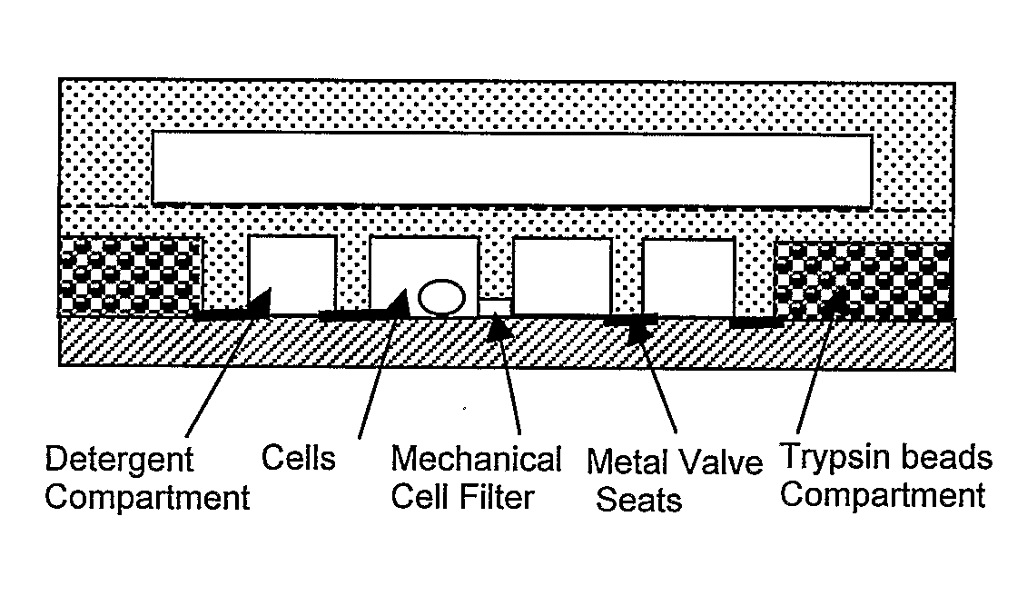
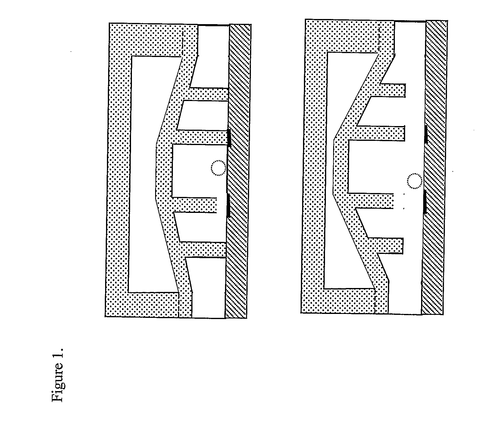
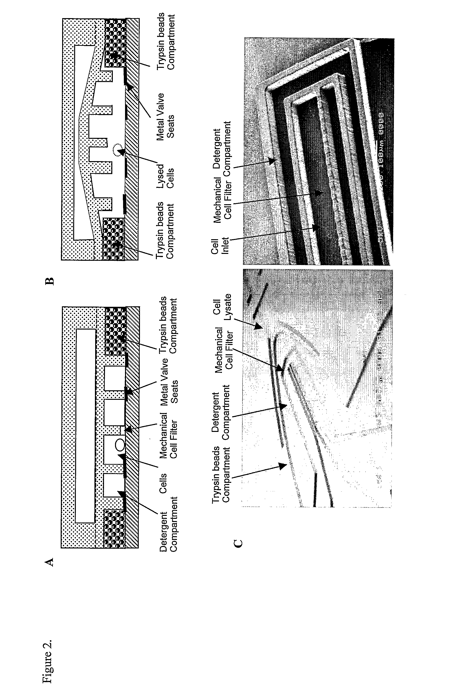
[0048]One embodiment of the invention features a two-layer PDMS device on glass, that incorporates a microfluidic network and a control layer, e.g., for handling small populations of suspended cells for sample preparation type applications (FIG. 3A). The two layers of PDMS were fabricated by casting the elastomer on separate photopatterned epoxy molds. The top, control layer contained a number of channels and the actuation chambers for the pneumatic valves. The bottom network layer contained the circuitry of channels of different widths and heights for the manipulation of cells and fluids. The control and network layers were bonded together and a membrane was formed between the actuation chambers in the top control layer and the bottom network layer (FIG. 3B). The two-layer construct was then selectively bonded on the top of a glass slide. The microstructures on the diaphragm were aligned to thin film metal patterns preventing the adhesion of the microstructure to the gl...
example 2
Sampling Precise Volumes from Cell Suspensions
[0054]Four barriers on separate membranes were combined to realize a T-junction type structure for sampling precise volumes from cell suspensions (e.g. whole blood). Two valves, their control chambers coupled, control the flow of the cell suspension along the vertical axis (FIG. 4A). A second pair of valves allowed the displacement of the precisely metered sample by flow of buffer along the horizontal axis into the outlet sampling channel (FIG. 4B). The microstructures on the valves, in the form of curved barriers defined the walls of a cylindrical chamber with a 30 nL volume (FIG. 4C). Repeated metering of whole blood was accomplished on the device by alternately operating the valves. The precision of the metering was verified by the absence of resident cells in the sampling chamber after the buffer wash (FIG. 4D).
[0055]The use of microstructured diaphragm for the implementation of four valves, in a chromatography T-junction-like design...
example 3
Cell Isolation
[0057]Several microstructures were combined on the same membrane for partial decoupling of cell movement and fluid flow. Two structures of different heights on the same membrane were used for concentrating a cell suspension, by splitting the liquid and the cells into distinct chambers (FIGS. 5A, 5E, and 5F). A first, leaky barrier, in resting position, allowed only the passage of fluid through 3×10 μm channels while mechanically blocking the cells. A second, fall barrier directed the leaked fluid into a drain channel. An additional microstructured diaphragm valve was used to control the flow in the drain channel independently (FIG. 5B). A cell suspension was introduced through the inlet channel, and cells were trapped at the leaky barrier. With the accumulation of cells at the first barrier, the flow was obstructed, because of the blocking of the small leaky channels. The accumulated cells were then transported into the outlet channel by briefly lifting and then quickl...
PUM
| Property | Measurement | Unit |
|---|---|---|
| angle | aaaaa | aaaaa |
| size | aaaaa | aaaaa |
| size | aaaaa | aaaaa |
Abstract
Description
Claims
Application Information
 - R&D
- Intellectual Property
- Life Sciences
- Materials
- Tech Scout
- Unparalleled Data Quality
- Higher Quality Content
- 60% Fewer Hallucinations
Browse by: Latest US Patents, China's latest patents, Technical Efficacy Thesaurus, Application Domain, Technology Topic, Popular Technical Reports.
© 2025 PatSnap. All rights reserved.Legal|Privacy policy|Modern Slavery Act Transparency Statement|Sitemap|About US| Contact US: help@patsnap.com


