
Spray distribution assembly, beverage brewer with spray distribution assembly and methods

a technology for beverage brewers and assembly parts, applied in the field of hot beverage brewers, can solve the problems of reducing the total quantity of hot water dispensed, clogging or partially obstructing the spray hole, consequential increase in the strength of the brewed beverage, etc., to reduce the amount of residual water, and reduce the effect of mineral deposits

Active Publication Date: 2009-09-10
FOOD EQUIPMEENT TECH COMPANY
View PDF25 Cites 19 Cited by
  • Summary
  • Abstract
  • Description
  • Claims
  • Application Information

AI Technical Summary

Benefits of technology

[0016]Preferably, the entire umbrella-like body is made entirely of hydrophobic, nonmetallic, solid material instead of a metal with only a coating of nonmetallic material to reduce the rate of heat flow to and from the body. In either event, the nonmetallic material is a polymer such as polypropylene that transfers heat more slowly than metal.
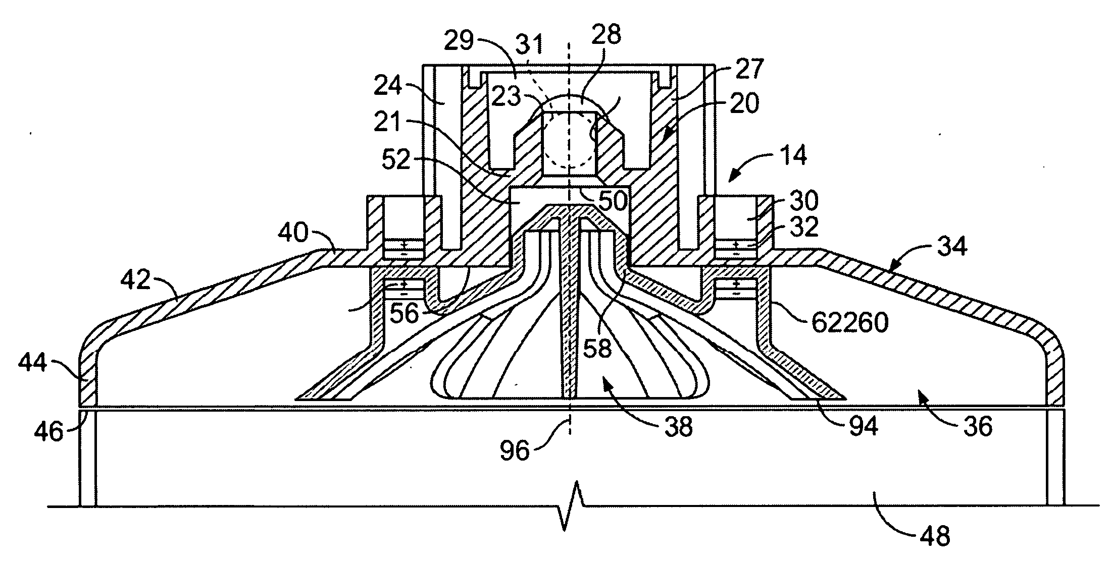
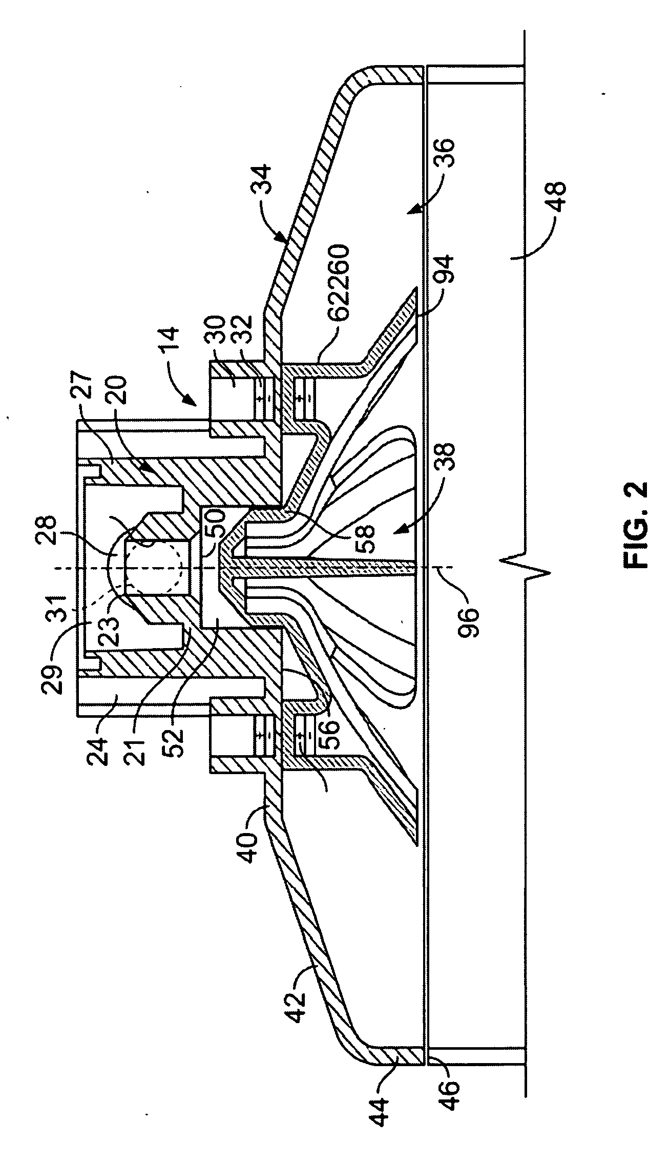
[0018]The objective is also achieved by providing a method for use in a hot water spray distribution assembly of a hot beverage brewer to distribute hot water from a hot water dispense system onto ingredient in a brew basket of the brewer by performance of the steps of (1) passing hot water from the dispense system to a core having at least one passageway extending along the core, (2) passing hot water from the core to a spray plate with an upwardly facing surface for receipt and distribution of hot water to the brew basket, said upwardly facing surface being made of hydrophobic, nonmetallic, solid, material, with a heat transfer characteristic that is less than metal, and (3) distributing the hot water across the hydrophobic, nonmetallic, solid material of the spray plate and off the spray plate onto the ingredient in the brew basket. Preferably, the entire spray plate is entirely made of the hydrophobic, nonmetallic, solid material, such as a polymer or polymer-like material such as polypropylene that transfers heat much more slowly than metal to reduce evaporation. Passing the hot water downwardly along the upwardly facing umbrella-like surface and off an outer edge of the spray plate to the ingredient instead of through small holes in a flat plate also reduces the amount of residual water remaining on the surface to further reduce the amount of water that is evaporated off of the surface to reduce mineral deposits.
[0020]Preferably, the other surface (c) is one of (1) downwardly, outwardly tapered, (2) convex, (3) tapered downwardly at an increasing taper as the distance from a central location increases, (4) segmented with elongate segments separated by relatively shorter segments that are joined to and between the elongate segments, and (5) formed with upwardly facing grooves that terminate at different radial distances from a central core. The entire spray plate is made entirely of hydrophobic, nonmetallic, solid material to reduce the transfer of heat from the hot water to the spray plate relative to metal and to reduce mineral encrustation. The nonmetallic material is one of (a) a polymer or polymer-like material, (b) a polypropylene or polypropylene-like material, (c) a plastic or plastic-like material with a heat transfer characteristic substantially smaller than metal, and (d) a plastic or plastic-like material that is hydrophobic.
[0023]Preferably, the step of passing includes the step of passing the water at rate adjacent the central portion that is slower than the rate of passing adjacent the peripheral edge. A core with radially, outwardly facing, peripheral grooves substantially fills the passageway except for gaps between the grooves and an interior surface of the passageway and the step of receiving the hot water includes receiving the hot water in a circular pattern surrounding a central axis of the passageway. The water is dropped off the peripheral edge of the top surface at different radial distances from the central portion. The top surface has a plurality of radially extending slots that in part define the peripheral edge and including the step of passing the water of the peripheral edge at locations along the slots. The peripheral edge in part forms a plurality of arcuate petal-like members the water is passed off the peripheral edge at the peripheral edge of the arcuate petal-like members. The peripheral edge varies inwardly and outwardly from the central portion and thus the water is dropped off the peripheral edge at a plurality of different radial distances from the central portion. In the preferred embodiment, the top surface has a plurality of upwardly facing elongate radial grooves and the step of receiving includes the step of receiving the hot water into the radial grooves and passing the hot water along the grooves to drop the water of the peripheral edge at the ends of the grooves, the ends of said grooves being located at different radial distances from the central portion. Evaporation and resultant mineral deposits are reduced by making the top surface, and preferably the entire plate, from hydrophobic, nonmetallic, solid, material, and the step of passing includes passing the hot water downwardly and outwardly along the hydrophobic, nonmetallic, solid, material, such a polypropylene to reduce mineral encrustation and heat absorption by the top surface.

Problems solved by technology

Due to the presence of lime, in various mineral forms and other minerals and mineral compounds, such as iron, dissolved in the hot water and the evaporation of the hot water in contact with the top and bottom surfaces of the spray plate and the inlets, outlets and side surfaces of the spray holes, calcium oxide, calcium sulfate, magnesium sulfate, calcium silicate and magnesium silicate and other mineral deposits build up on these surfaces and over time can clog entirely or partially obstruct the spray holes.
However, partial or complete clogging of the spray holes from liming will result in a reduction of the total quantity of hot water dispensed and a consequential increase in the strength of the brewed beverage over time.
In addition, the degree of control over the hot water dispense time period and the total quantity of hot water dispensed that is needed for production of brewed beverage of uniform and preselected characteristics is lost.
Ultimately, if the spray plate is not cleaned of the liming residue, the entire array of spray holes can become so clogged that the brewer will cease to function completely function.
Such cleaning is labor intensive and disables the brewer from operation during the cleaning.
Another problem with know spray head assemblies is that the velocity of the water droplets onto the top surface of the ingredient in the brew basket is directly related to the water pressure from the hot water dispense system and may impact the surface of the ingredient with sufficiently high impact energy to disadvantageously mechanically disturb the layer of ingredient and create undesirable splatter.

Method used


Image

  • Spray distribution assembly, beverage brewer with spray distribution assembly and methods
  • Spray distribution assembly, beverage brewer with spray distribution assembly and methods
  • Spray distribution assembly, beverage brewer with spray distribution assembly and methods

Examples


Embodiment Construction

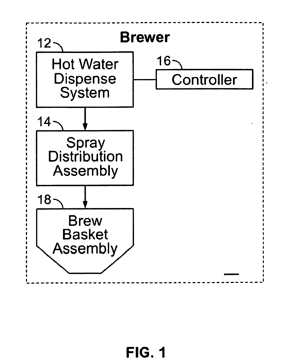
[0049]Referring to FIG. 1, a preferred embodiment of the hot beverage brewer 10 of the present invention is seen to have a hot water dispense system 12 that selectively passes hot water from a hot water tank to a spray distribution assembly 14 under control of a controller 16. The hot water is passed from the spray distribution assembly 14 to the brew basket assembly 18. The brew basket assembly 18 has an internal filter holder that contains the beverage ingredient while hot water is passed through the ingredient to brew the hot beverage, such as hot coffee or tea, or hot tea extract used to make iced tea. The hot beverage or extract is then passed through a drain hole at the bottom of the brew basket 14 into a suitable beverage container. In the case of an iced tea brewer, cold water is also added to the beverage container and mixes with the abstract.

[0050]The hot water dispense system 12, the controller 16 and the brew basket assembly are well know in their structures and function...


PUM

PropertyMeasurementUnit
widthaaaaaaaaaa
hydrophobicaaaaaaaaaa
heat transferaaaaaaaaaa

Abstract

A hot beverage brewer (10) having a hot water dispense system (12), a brew basket assembly (18) for holding ingredient to be mixed with the hot water to make a freshly brewed hot beverage and a controller (16) for controlling the delivery of hot water from the hot water dispenser system to the brew basket (18) with a spray distribution assembly (14) having a spray head (20) having a generally vertical passageway (22) for receipt of hot water and an umbrella-like member (34). A spray plate (38) mounted beneath the umbrella-like member (34) has a downwardly, outwardly tapered top surface with radiating, downwardly directed, upwardly facing grooves and an upwardly standing central core (58) snuggly received within the passageway (22) joined to the underside of the top of the umbrella-like member (34) with a plurality of vertical radially, outwardly facing grooves (68) extending from the top to the bottom to form a plurality of peripheral closed channels for passing hot water to upwardly facing grooves (74) of the umbrella-like body. Mineral encrustation is reduces by making the spray plate (38) of a material, such a polypropylene, that is hydrophobic and has a heat transfer coefficient that is substantially less than that of metal to reduce evaporation of residual water from the surface of the spray plate. Alternatively, the spray plate (38) is coated with PTFE or the like. The spray plate (38) has a surrounding outer edge that varies in radial distance from the core around a periphery of the umbrella-like body to form a plurality of radially extending pedals (80) separated by a plurality of slots (82). Tooless securing means (32, 60) permits relative rotation of the core within the passageway (22) scrape clean the core and passageway of residue. A method provides for retrofitting flat plate spray plate type distribution systems with the spray plate (38) though the use of an adapter (158)

Description

CROSS-REFERENCE TO RELATED APPLICATION[0001]This application is a continuation-in-part of, and claims the benefit under 35 U.S.C. 120 of pending application Ser. No. 10 / 849,387, of the present co-inventors, filed May 19, 2004 and entitled “Beverage Brewer With Spray Distribution Assembly and Method”, which is hereby incorporated by reference, and which, in turn, claims under 35 USC 119(e) the benefit of U.S. provisional applications Ser. No. 60 / 474,088, filed May 28, 2003, and Ser. No. 60 / 562,066, filed Apr. 14, 2004, both of which are hereby incorporated by reference.BACKGROUND OF THE INVENTION[0002]1. Field of the Invention[0003]This invention generally relates to hot beverage brewers, such as hot coffee brewers and iced tea abstract brewers and hot tea brewers and, more particularly, to such brewers of the type that distribute hot water by means of a spray plate assembly upon ingredient contained within a brew basket to dissolve the ingredient to make the brewed beverage or brewe...

Claims


Application Information

Patent Timeline
Patent Type & Authority Applications(United States)
IPC IPC(8): A23L1/48A47J31/00B23P6/00A23L35/00
CPCY10T29/49721A47J31/3671A47J31/465A47J31/46
Inventor WROBLEWSKI, LESZEK M.LASSOTA, ZBIGNIEW G.
Owner FOOD EQUIPMEENT TECH COMPANY
Learn More