Enhanced Heat Transfer Tube and Manufacture Method Thereof

a technology of heat transfer tube and heat exchange coefficient, which is applied in the direction of manufacturing tools, coatings, lighting and heating apparatus, etc., can solve the problems of significant change in heat exchange coefficient and no suggestion of a process through which a phase change heat exchange coefficient can be significantly improved, so as to enhance the forced convention heat exchange out of the tube, improve the fluid disturbance, and increase the heat exchange area

Active Publication Date: 2009-09-17
JIANGSU CUILONG PRECISION COPPER TUBE CORP
View PDF12 Cites 12 Cited by
  • Summary
  • Abstract
  • Description
  • Claims
  • Application Information

AI Technical Summary

Benefits of technology

[0024]Compared with fin tubes in prior arts, embodiments of the present enhanced heat transfer tube can have the advantage that the microscale channel is formed on at least one lateral surface of the outer fin to help increase the heat exchange area of the outer fin surface, improve the fluid disturbance, enhance the forced convention heat exchange out of tube, and significantly improve the heat transfer coefficient. When such an enhanced heat transfer tube is applied on an evaporator, the microscale channel can greatly increase the number of the nucleation sites, so as to enhance boiling heat exchange in condition of low heat flux density. When such an enhanced heat transfer tube is applied on a condenser, the microscale channel can improve distribution of liquid membrane thickness on outer fin surface to enhance condensing heat exchange.

Problems solved by technology

However, in the disclosed references, there is no suggestion for outer fin structure on the outer tube of the heat transfer tubes for evaporators and condensers which can improve the phase change heat exchange coefficient significantly.
Additionally, there is no suggestion of a process through which a phase change heat exchange coefficient can be significantly improved by machining outer fin surface of the enhanced heat transfer tube via appropriate mechanical machining.

Method used


Image

  • Enhanced Heat Transfer Tube and Manufacture Method Thereof
  • Enhanced Heat Transfer Tube and Manufacture Method Thereof
  • Enhanced Heat Transfer Tube and Manufacture Method Thereof

Examples


embodiment 2

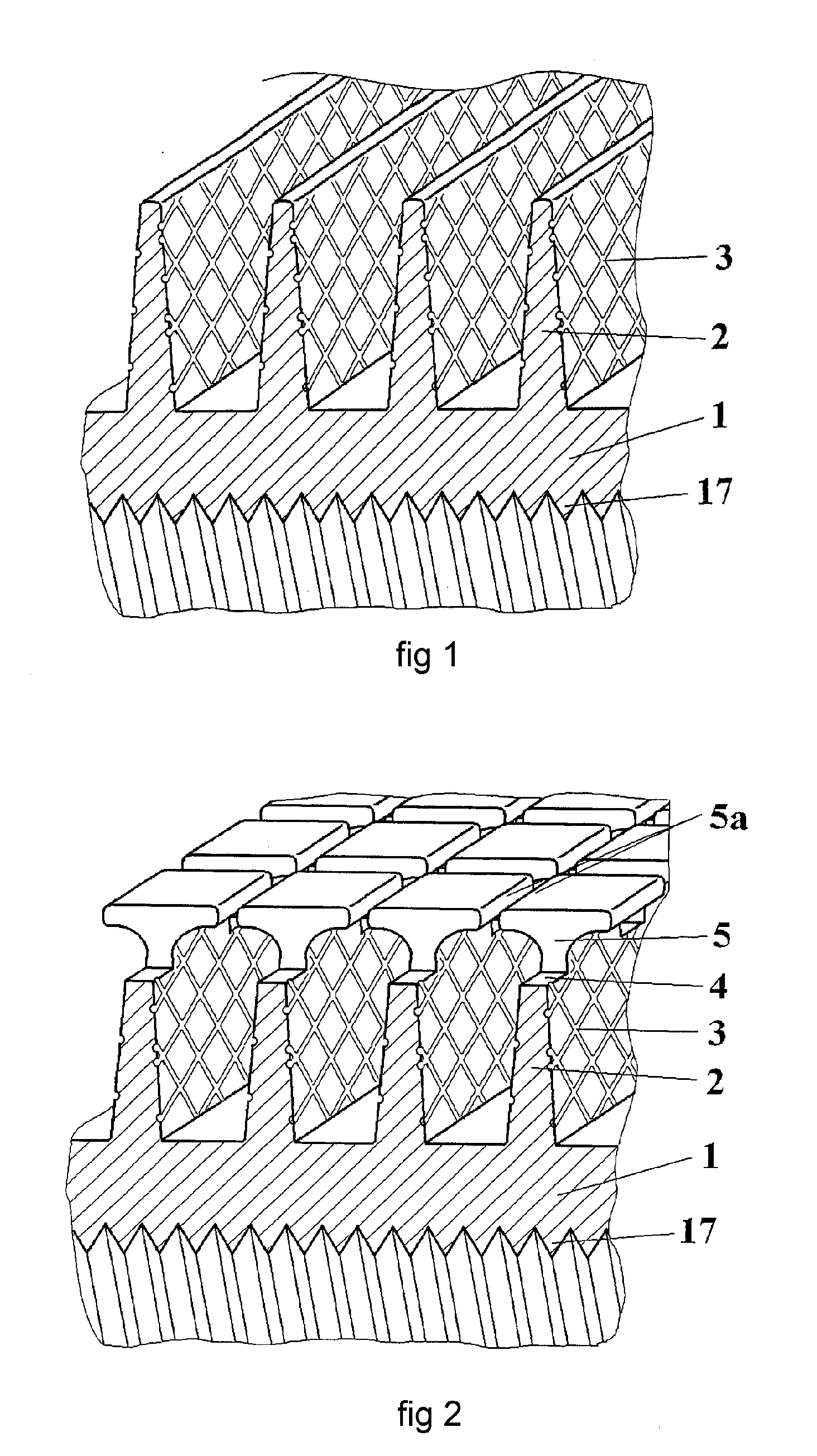
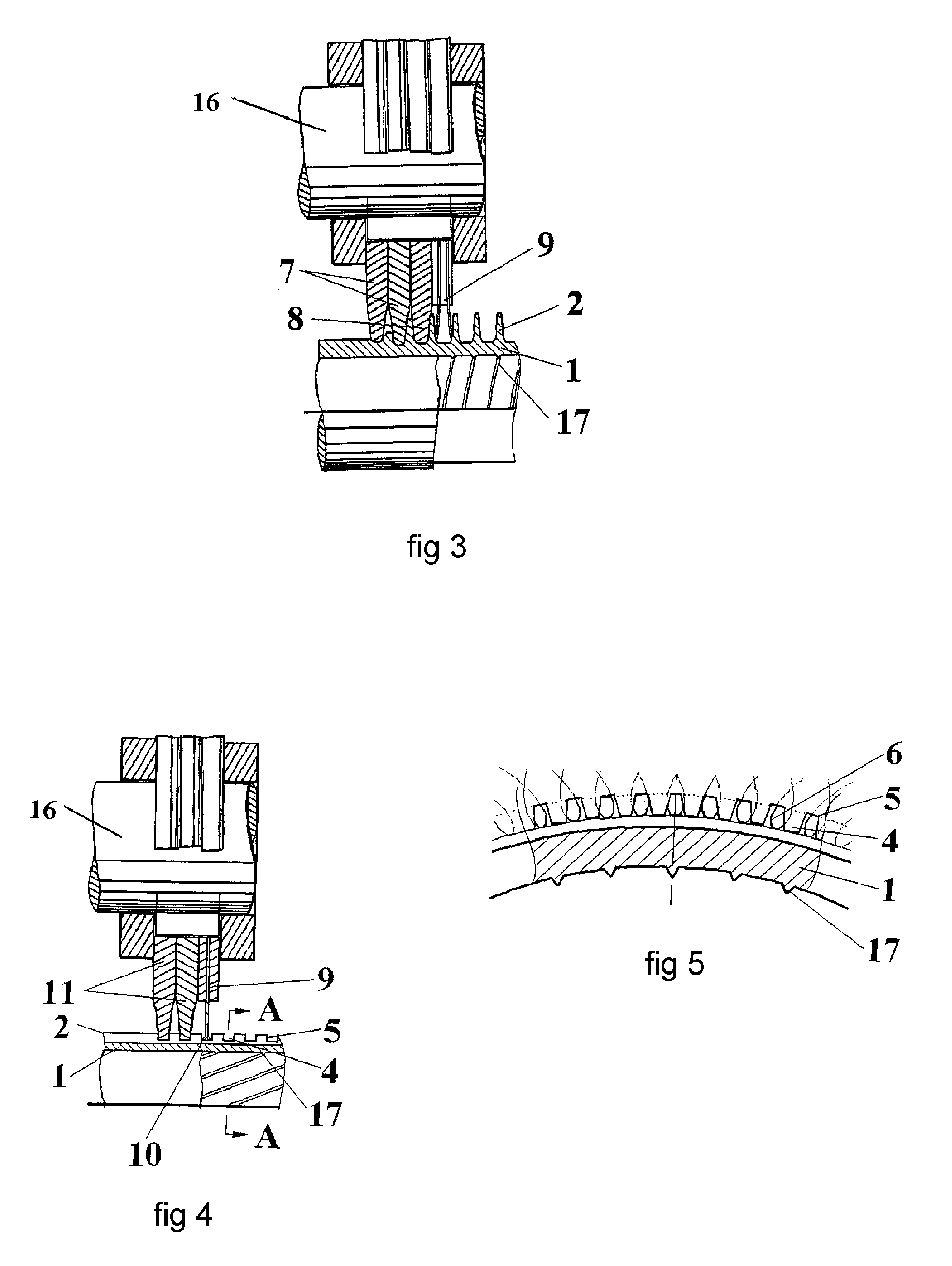
[0040]Referring to FIG. 3 and FIG. 6, an outer fin grooving tool 7, an outer fin forming tool 8, and a microscale channel grooving tool 9 can provide a tool set. Such a tool set can be fitted on a tool support 16 (also called tool shaft), in which multiple blades 10 (as shown in FIG. 6) are uniformly provided on the edge of the microscale channel grooving tool 9. The outer fins 2 can be formed by extrusion on a tube body 1.

[0041]In some embodiments, the diameter of the tube body 1 at the root of the outer fin 2 can be 20 mm. As the tube body 1 rotates relatively to the tool set, the outer fin 2 with height of 2 mm is formed by the outer fin grooving tool 7 and the outer fin forming tool 8, and microscale channels 3 with channel width of 0.08 mm, channel depth of 0.05 mm, and average channel interval of 0.5 mm are orderly carved on the lateral surface of the outer fins 2 by the blades 10 (as shown in FIG. 6) on the microscale channel grooving tool 9. Here, the average channel interva...

embodiment 3

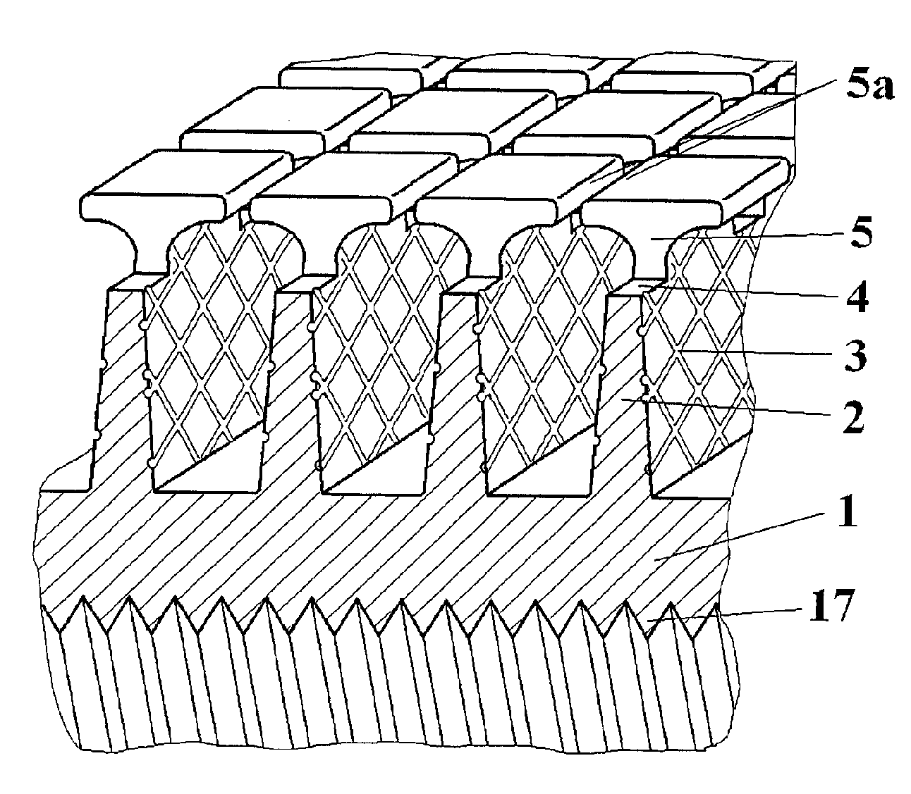
[0049]Referring to FIG. 4 and FIG. 5 together with FIG. 2, the manufacture of the inventive enhanced heat transfer tube as shown in FIG. 2 for condenser tube is taken as example.

[0050]The detailed structure comprises a tube body 1, outer fins 2 formed on outside wall surface of the tube body 1, notches 4 cut on the outer fins 2, and tooth platforms 5 formed between two adjacent notches 4. The depth of the notch 4 is smaller than the height of the outer fin 2. The notch 4 and the tooth platform 5 can constitute the outer fin 2 into sawtooth shape. One or two arc microscale channels 6 (as shown in FIG. 5) which can be extended from the root to the top of the tooth platform 5 are provided on the surface of the tooth platforms 5 opposite at two sides of the notch 4. The outer fins 2 have height of 1.2 mm, the tooth platforms 5 have height of 0.8 mm, the microscale channels 3 and the arc microscale channels 6 have channel width of 0.05 mm and channel depth of 0.01 mm.

[0051]In manufacture...

embodiment 4

[0055]Still referring to FIG. 4 and FIG. 5 together with FIG. 2, the manufacture of the inventive enhanced heat transfer tube as shown in FIG. 2 for evaporator tube is taken as example.

[0056]This heat transfer tube comprises a tube body 1, outer fins 2 formed on the outer wall surface of the tube body 1, dense microscale channels 3 formed on the lateral side of the outer fins 2, notches 4 cut on the outer fins 2, and tooth platforms 5 formed between two adjacent notches 4. The depth of the notch 4 is smaller than the height of the outer fin 2. The notch 4 and the tooth platform 5 constitute the outer fin 2 into sawtooth shape.

[0057]A flat roller can be adopted for extending the material of the top of the tooth platform 5 toward two sides to form fin top edge 5a. The fin top edge 5a mutually cooperates with the fin top edge 5a formed by material of the top of the tooth platform 5 also extending toward two sides, to make space between two adjacent outer fins 2 form cavity structure wh...


PUM

PropertyMeasurementUnit
depthaaaaaaaaaa
depthaaaaaaaaaa
widthaaaaaaaaaa

Abstract

A heat transfer tube can comprise a tube body, and outer fins integrated with the tube body which are formed by allowing material on the tube body to extend along radial direction of the tube body and wind and extend around the tube outer surface in helical manner, wherein microscale channels are formed on at least one lateral surface of the outer fin. The invention has the advantage that the microscale channel is formed on at least one lateral surface of the outer fin to help increase the heat exchange area of the outer fin surface, improve the fluid disturbance, enhance the forced convention heat exchange out of tube, and significantly improve the heat transfer coefficient; when the enhanced heat transfer tube in the present invention is applied on an evaporator, the microscale channel can greatly increase the number of the nucleation sites, so as to enhance boiling heat exchange in condition of low heat flux density; when the enhanced heat transfer tube in the present invention is applied on a condenser, the microscale channel can improve distribution of liquid membrane thickness on outer fin surface to enhance condensing heat exchange.

Description

PRIORITY INFORMATION[0001]The present application is based on and claims priority under 35 U.S.C. §119(a-d) to Chinese Patent Application No. 200810019684.4, filed on Mar. 12, 2008, the entire contents of which is expressly incorporated by reference herein.BACKGROUND OF THE INVENTIONS[0002]1. Field of the Inventions[0003]The present inventions relate to enhanced heat transfer tubes which can be used as, for example, heat exchange elements of evaporators and condensers for refrigeration and air conditioning systems, as well as manufacture methods for the heat transfer tube, which falls into the technical field of heat exchange element and manufacture technique.[0004]2. Description of the Related Art[0005]Liquid boiling or condensing on outer surfaces of tube bundles is involved in the fields of refrigeration, air conditioning, process engineering, petrochemical industry, and energy and power engineering. For the evaporators and condensers used in refrigeration and air conditioning sy...

Claims


Application Information

Patent Timeline
Patent Type & Authority Applications(United States)
IPC IPC(8): F28F1/00B21D21/00
CPCB21C37/26B23D5/00F28F1/36F28F1/42Y10T29/49391F28F13/187F28F2215/10Y10T29/49382F28F1/422
Inventor LU, MINGHUAZHANG, CHUNMINGLUO, XINGZHOU, HAOPING
Owner JIANGSU CUILONG PRECISION COPPER TUBE CORP
Why Eureka
Try Eureka