

Injector for a fuel injection system
- Summary
- Abstract
- Description
- Claims
- Application Information
AI Technical Summary
Benefits of technology
Problems solved by technology
Method used
Image

Examples
Embodiment Construction
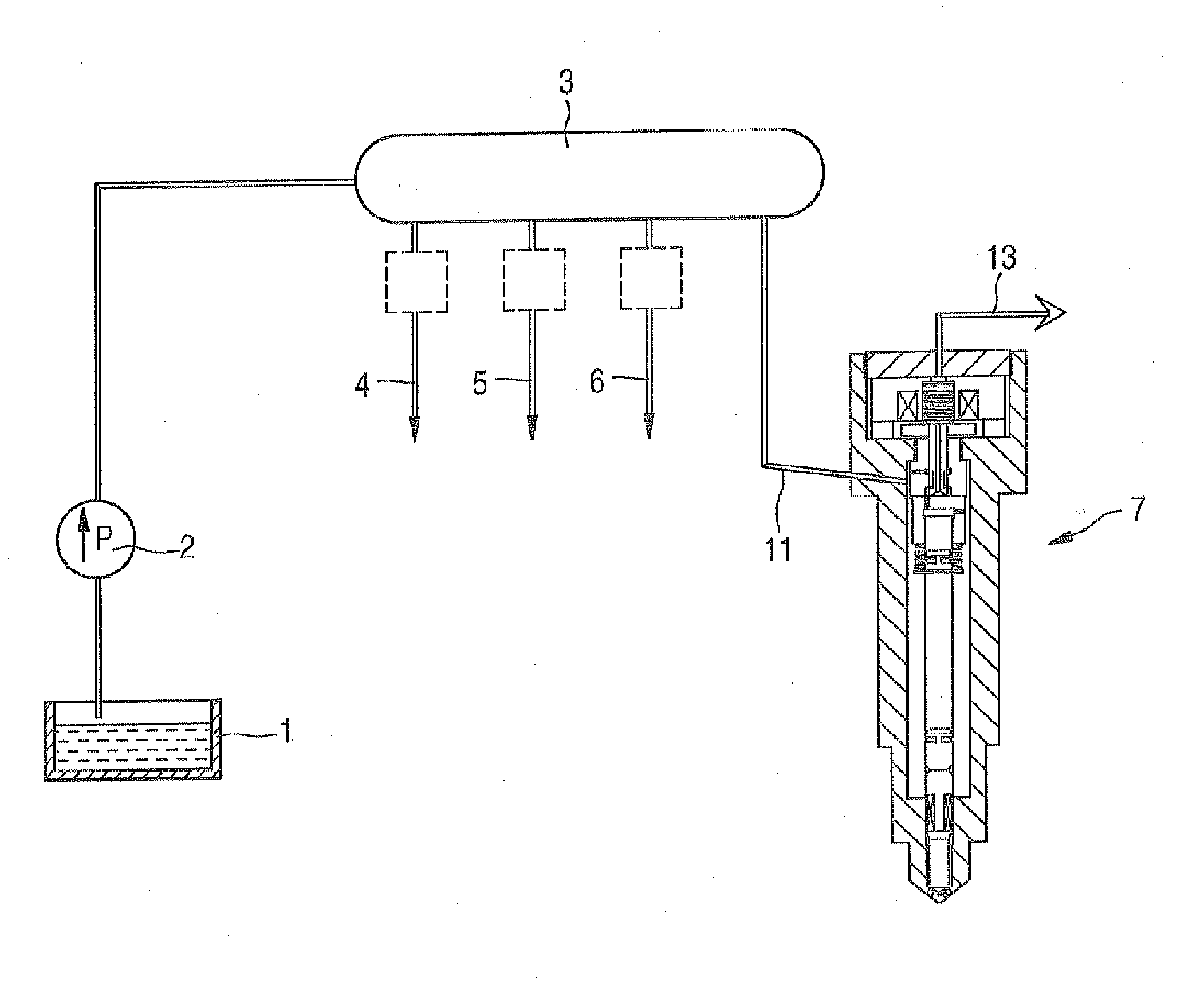
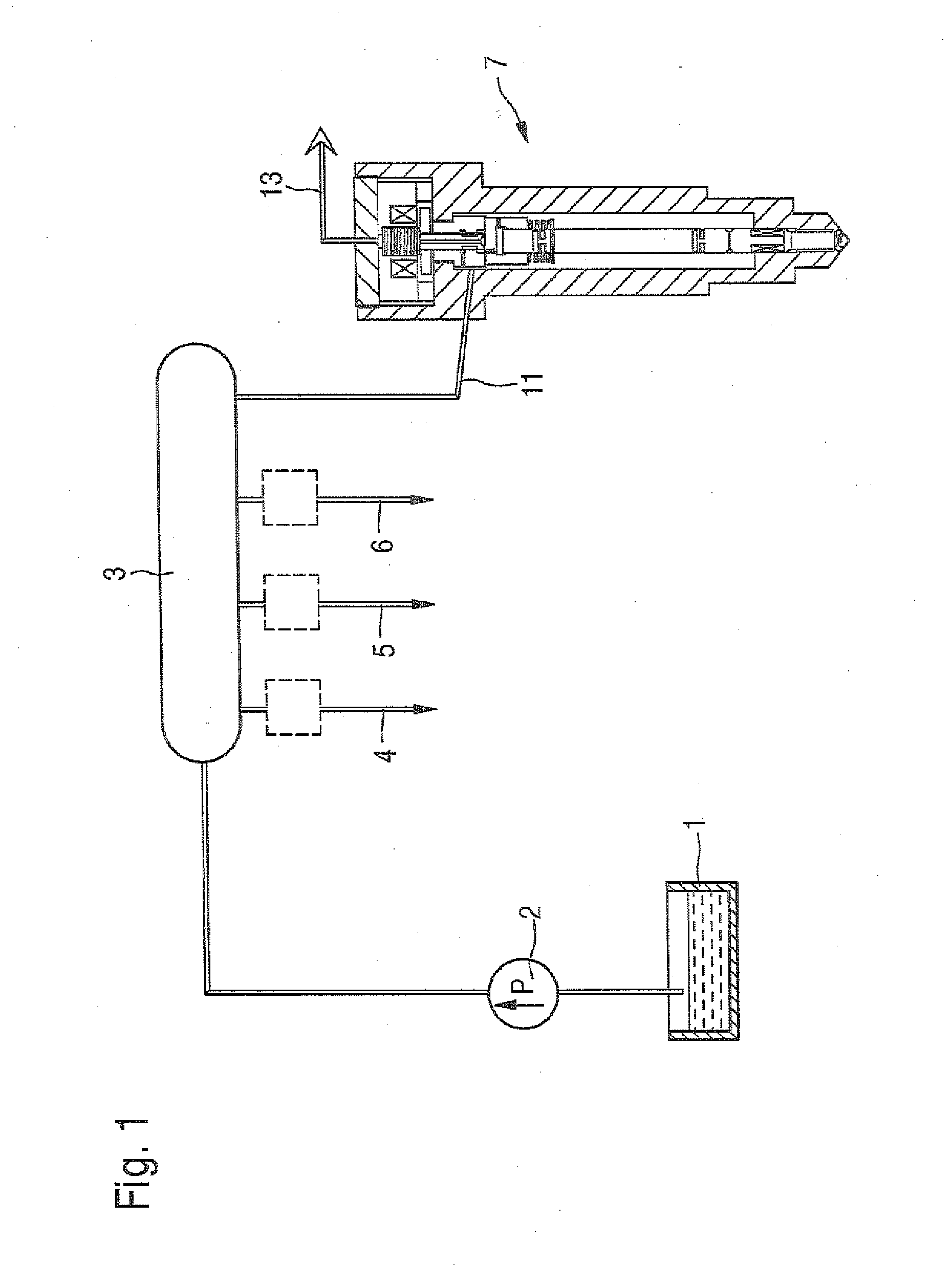
[0022]In FIG. 1, a common rail injection system is shown schematically. From a fuel tank 1, fuel is pumped with the aid of a pump unit 2 into a high-pressure fuel reservoir 3 and subjected to high pressure. The fuel subjected to high pressure is then allocated as a function of demand to the individual cylinders of the internal combustion engine to be supplied. The injection of the fuel subjected to high pressure is effected through injectors 4, 5, 6 and 7. In FIG. 1, only the injector 7 is shown, for the sake of simplicity.
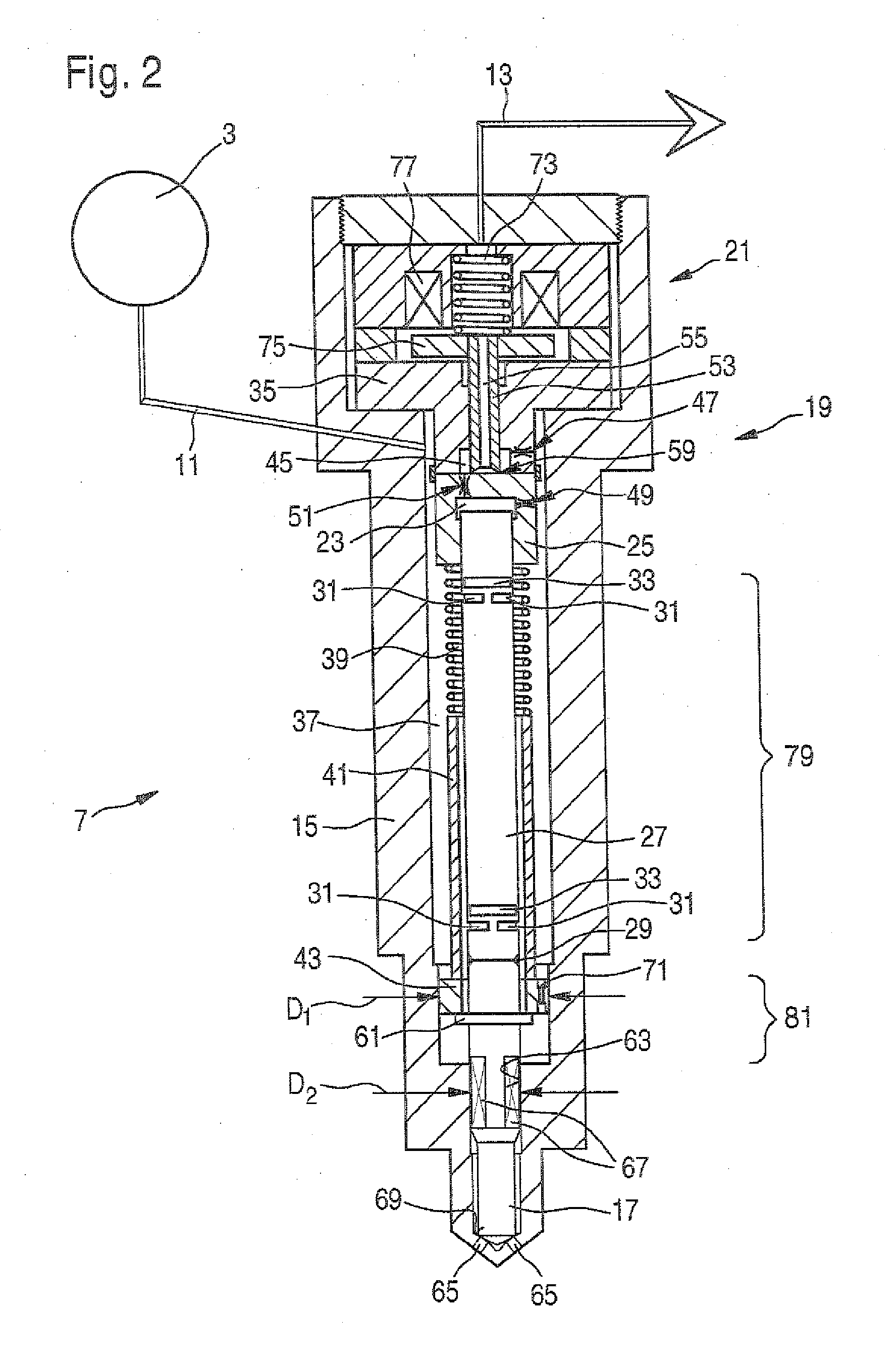
[0023]The injector 7 communicates with the common rail 3 via a high-pressure connection 11. The injector 7 moreover communicates hydraulically with the tank 1 via a fuel return 13, which is virtually pressureless. The injector 7 will be described in further detail below in conjunction with FIGS. 2 and 3.
[0024]The injector 7 includes a housing 15, in which a nozzle needle 17 is guided. A control valve 19 according to the invention and an electromagnetic actuator 21...
PUM
 Abstract
Description
Claims
Application Information