
Illumination device comprising a light source and a light-guide

a technology of light source and light guide, which is applied in the direction of semiconductor devices for light sources, lighting and heating apparatus, instruments, etc., can solve the problems of sacrificing one or more criteria, affecting the overall efficiency of the light source, so as to achieve the effect of shortening the traversed path of light, increasing the homogeneity of light radiation pattern, and saving spa

Active Publication Date: 2009-09-17
SIGNIFY HLDG BV
View PDF11 Cites 59 Cited by
  • Summary
  • Abstract
  • Description
  • Claims
  • Application Information

AI Technical Summary

Benefits of technology

[0008]The invention provides a narrow beam illumination device that has the desired compactness of existing lamp form factors, like a PAR lamp, with the ability to vary and control color and power.
[0009]By applying a mirror to the second end-portion of the light-guide, the light is reflected back into the light-guide, effectively lengthening the traversed path of the light inside the light-guide. From an optical point of view, the light-guide is folded through the application of a mirror to its end face. A considerable advantage of the above-described solution is the more economical use of the space inside the secondary optical system. This creates effectively the extended length that otherwise necessarily would have been protruded to the rear.
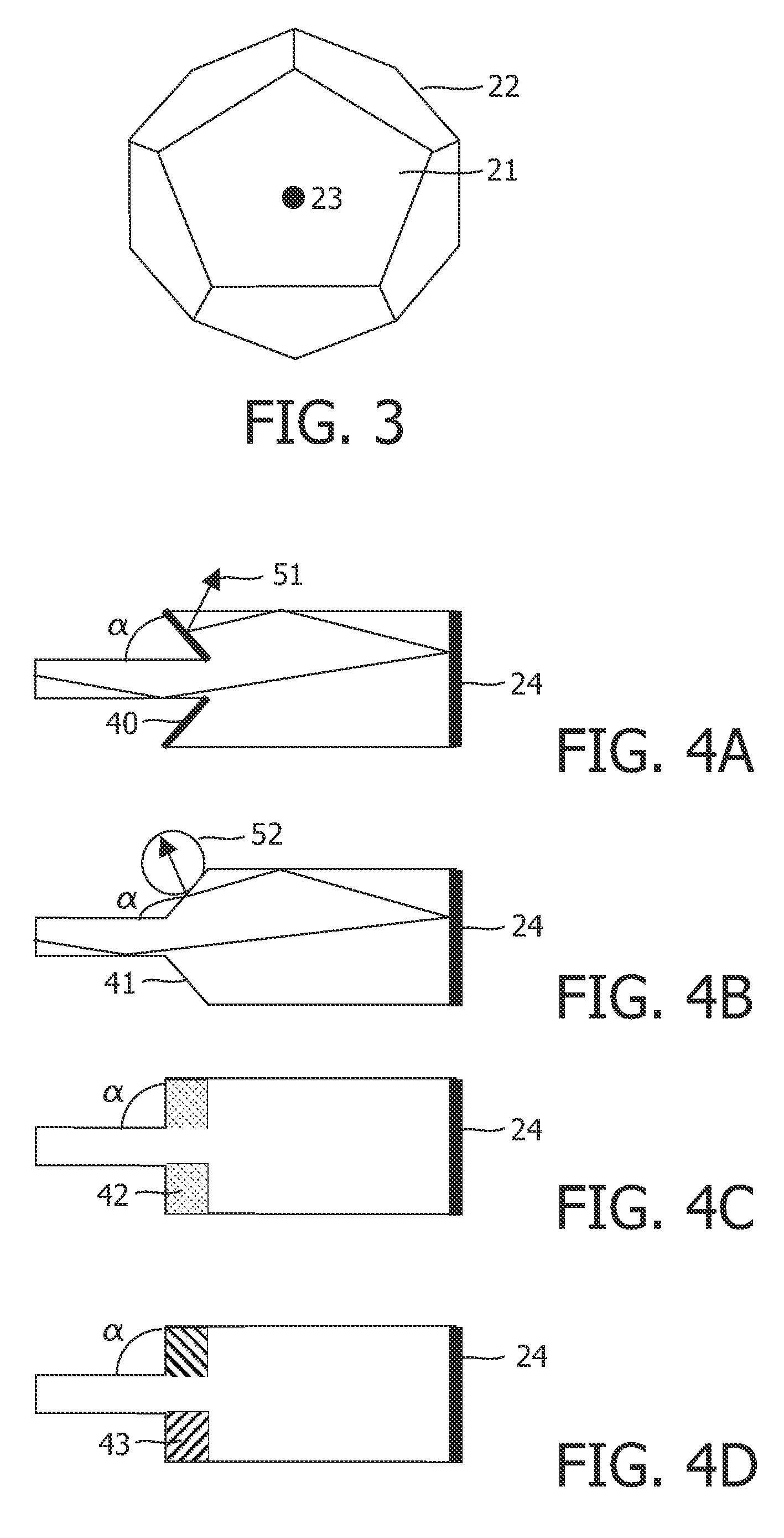
[0010]In an embodiment of the present invention the homogeneity of the light radiation pattern is further increased by providing an illumination device where the light-guide has a polygonal cross section orthogonal to the optical axis.

Problems solved by technology

The problem especially exists when utilizing a multi-color array of LED chips for producing white light in a device with beam generating optics.
Several solutions have been proposed to solve the mixing problem, but they all have the disadvantage that one or more criteria are sacrificed, such as: the size of the luminary, the angular width of the beam or the overall efficiency.
Furthermore, some mixing solutions have very stringent alignment requirements.
However, the disadvantage of these mixing rods lies in the fact that good color mixing requires a large length over thickness ratio.
However this will also decrease the in-coupling efficiency and thus the overall efficiency of the device.

Method used


Image

  • Illumination device comprising a light source and a light-guide
  • Illumination device comprising a light source and a light-guide
  • Illumination device comprising a light source and a light-guide

Examples


Embodiment Construction

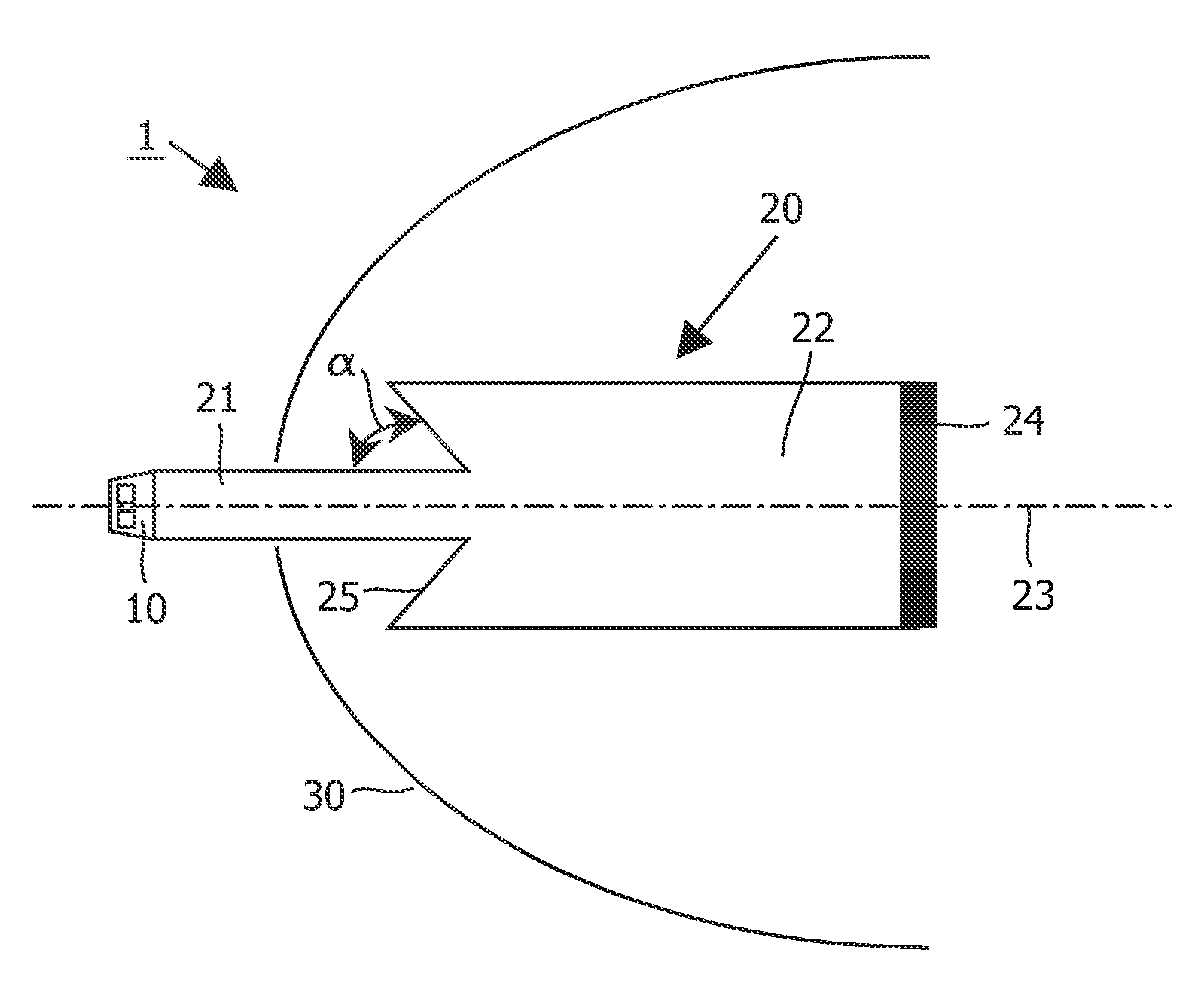
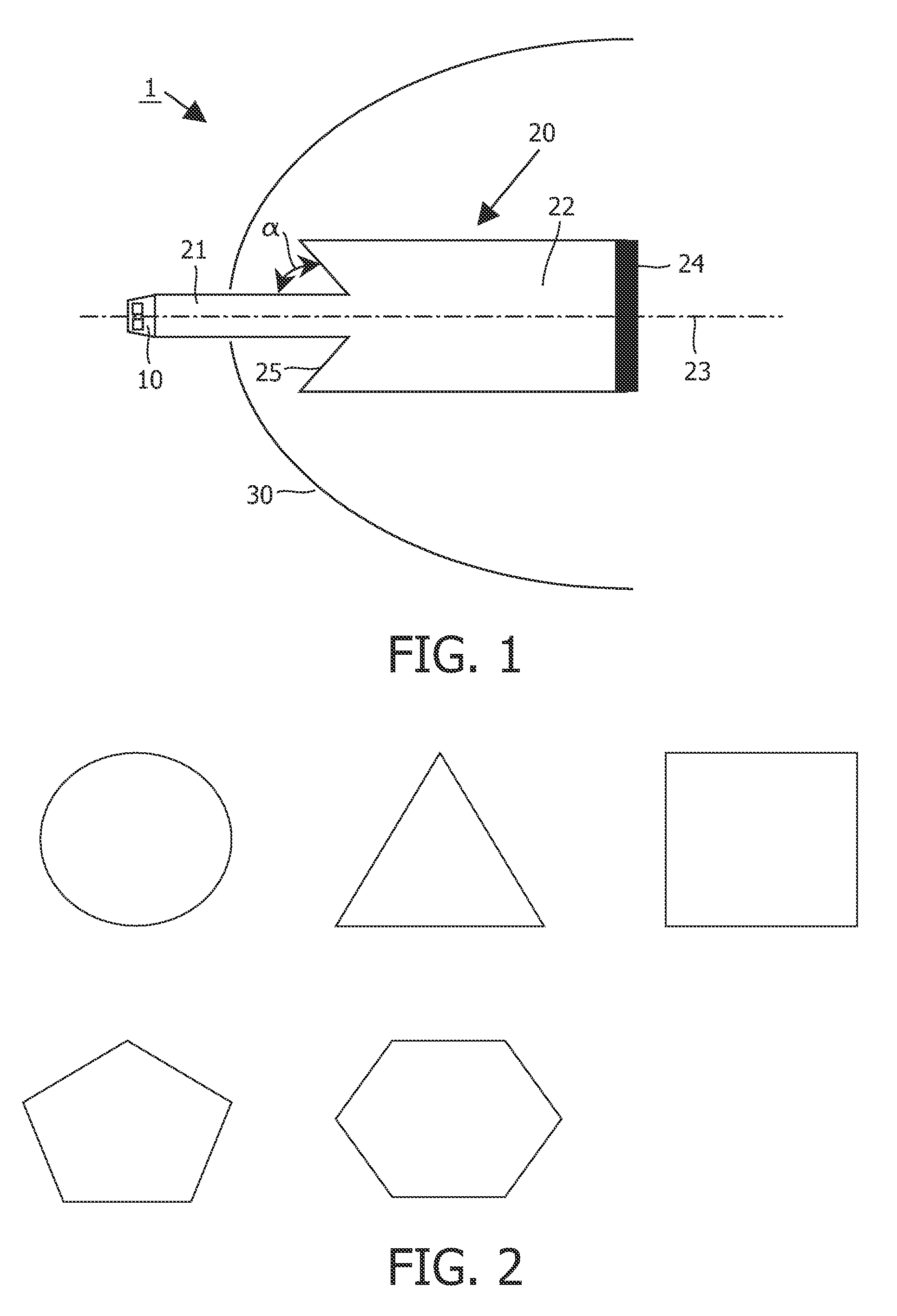
[0025]FIG. 1 shows a longitudinal cross section through a first embodiment of an illumination device 1 according to the invention. The illumination device comprises a semiconductor light source 10 for generating light, a primary optical system 20 for feeding the light to a secondary optical system 30, which is provided for radiating the light and for achieving a desired radiation pattern.

[0026]The semiconductor light source 10 comprises at least one light-emitting element, like e.g. a LED or a Laser-Diode.

[0027]The primary optical system 20 comprises a light-guide with a first end-portion 21, a second end-portion 22, an optical axis 23 extending between the first and second end-portions, a mirrored end-face 24 and an out-coupling structure 25 located between the first and second end-portions for directing out-coupled light into the secondary optical system 30.

[0028]The secondary optical system 30 comprises of a reflector and / or a lens system, designed to achieve a desired light radi...


PUM


Abstract

Proposed is an illumination device (1), comprising a semiconductor light source (10) for generating light, a primary optical system (20) for feeding the light to a secondary optical system (30), which is provided for radiating the light and for achieving a desired radiation pattern. The semiconductor light source may comprise LEDs and / or Laser-Diodes. The primary optical system comprises a light-guide with a mirrored end-face (24) and an out-coupling structure (25) for directing light into the secondary optical system. The mirrored end-face optically folds the light-guide, effectively extending the length over which the light is advantageously homogenized inside the light guide. Furthermore, optically folding the light-guide makes more economical use of the space inside the secondary optical system. This is especially advantageous when designing an LED based retrofit for existing form factors of halogen based illumination devices.

Description

FIELD OF THE INVENTION[0001]The invention relates to an illumination device comprising a semiconductor light source means, a primary optical system comprising a light-guide having a first end-portion, a second end-portion, an optical axis extending between the first and second end-portions, and an out-coupling structure located between the first and second end-portions for out-coupling light, the light source means being arranged for coupling light into the first end-portion, a secondary optical system, the light-guide being arranged to direct out-coupled light into the secondary optical system for achieving a desired light radiation pattern. Such an illumination device is especially dimensioned for replacing a conventional illumination device using an incandescent-, halogen- or gas-discharge bulb or burner.BACKGROUND OF THE INVENTION[0002]An embodiment of an illumination device of the kind set forth is known from application WO2006054199. That document discloses a light source comp...

Claims


Application Information

Patent Timeline
IPC IPC(8): F21V7/04F21K99/00
CPCF21K9/52G02B6/0033F21Y2101/02F21K9/61F21Y2115/10
Inventor VAN DUIJNEVELDT, WIDO
Owner SIGNIFY HLDG BV
Learn More