Optical pickup and optical data processing device using the same

a technology of optical data processing and optical pickup, applied in the field of optical pickup, can solve the problems of inability to precisely track the servo, inability to accurately track the servo, and inability to output suitably amplified track error signals, so as to prevent the deterioration of track error signals

Inactive Publication Date: 2009-09-17
RICOH KK
View PDF21 Cites 2 Cited by
  • Summary
  • Abstract
  • Description
  • Claims
  • Application Information

AI Technical Summary

Benefits of technology

[0022]Because of these reasons, the present inventor recognizes that a need exists for an image pickup including an optical element which reduces an interfering light beam caused by an adjacent layer of an optical recording medium, prevents deterioration of track error signals ascribable to the adjacent layer, particularly corrects the cross talk between layers as a cor

Problems solved by technology

Therefore, the offset component contained in the push-pull signal Sa is completely removed or significantly reduced, which leads to output of a suitably amplified track error signal.
In particular, when L12_zero dimensional light beam and the L21_zero dimensional light beam are caused to vary due to variation in thickness between layers, a phenomenon in whic

Method used


Image

  • Optical pickup and optical data processing device using the same
  • Optical pickup and optical data processing device using the same
  • Optical pickup and optical data processing device using the same

Examples


embodiment 1

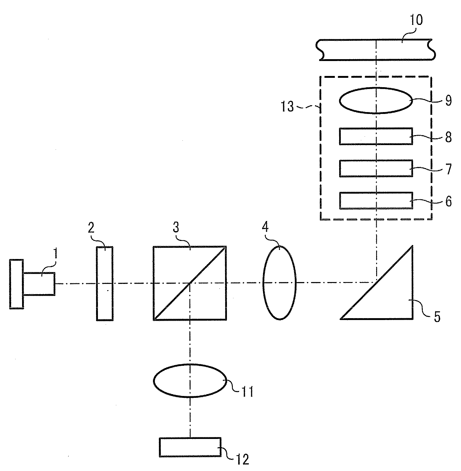
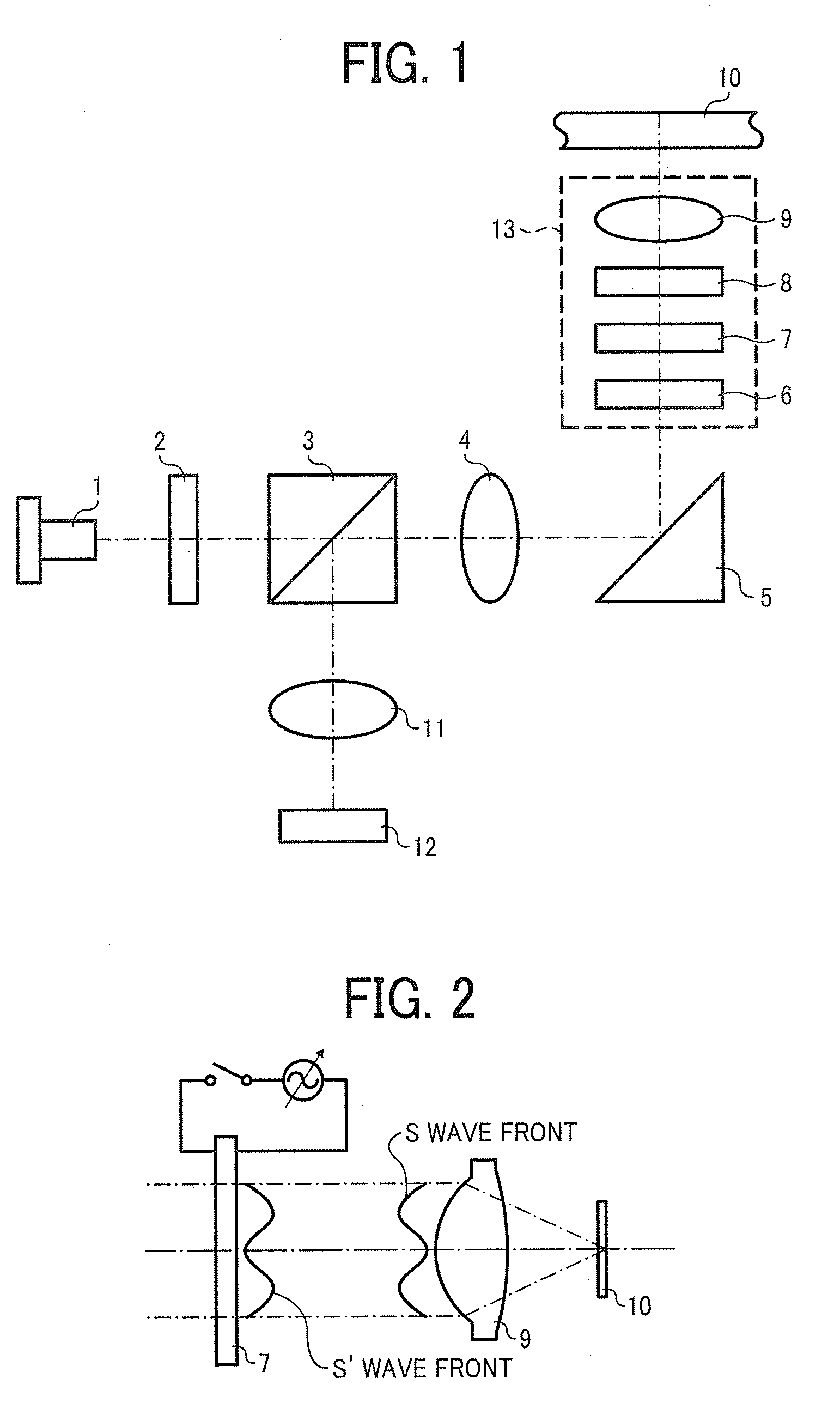
[0053]FIG. 1 is a schematic diagram illustrating the pickup of Embodiment 1 of the present invention. In FIG. 1, a numeral reference 1 represents a semiconductor 1, a numeral reference 2 represents a diffraction element for 3 beams, a numeral reference 3 represents a polarization beam splitter, a numeral reference 4 represents a collimate lens, a numeral reference 5 represents a polarization mirror, a numeral reference 6 represent a correction element to reduce cross-talk, a numeral reference 7 represents a crystal liquid element to correct spherical aberration, a numeral reference 8 represents a ¼ wavelength board, a numeral reference 9 represents an objective lens, a numeral reference 10 represents an optical recording medium, a numeral reference 11 represent a detection lens, a numeral reference 12 represents a light reception element, and a numeral reference 13 represent an actuator. The optical recording medium 10 has data recording layers L1 and L2 from the objective lens 9 si...

embodiment 2

[0095]FIG. 6 is a schematic diagram illustrating the optical pickup of Embodiment 2 of the present invention. The difference between the structure of Embodiment 1 and that of Embodiment 2 is that while the optical pickup of Embodiment 1 is exclusive for one optical recording medium (e.g., BD optical recording media), the optical pickup of Embodiment 2 deals with reading and writing data signals on two different kinds of optical recording media, e.g., BD optical recording media and DVD recording media.

[0096]A semiconductor 14 is arranged in Embodiment 2 instead of the semiconductor lased 1 of FIG. 1. Furthermore, each optical element deals with two wavelengths. The semiconductor laser 14 is a two wavelength light source unit which accommodates a light source for BD formed of a laser diode which emits a light beam in the wavelength band of 405 nm and a light source for DVD formed of a laser diode which emits a light beam in the wavelength band of 660 nm. The two wavelength light sourc...

embodiment 3

[0308]FIG. 15 is a block chart illustrating an optical data processing device of Embodiment 3 of the present invention. As illustrated in FIG. 15, the optical data processing device is a device which records and plays data signals for an optical recording medium 10 and includes an optical pickup 41 corresponding to the optical pickups described above; a spindle motor 48 to rotate the optical recording medium 10; a transfer motor 42 to move the optical pickup 41 to and from the inner and outer circle of the optical recording medium 10; a modulation and demodulation circuit 44 to perform predetermined modulation and demodulation; a servo control circuit 43 to servo-control the optical pickup 41; and a system controller 47 to control the entire optical data processing device.

[0309]The servo control circuit 43 controllably drives and rotates the spindle motor 48 at a predetermined rotation number. The optical recording medium 10 to be recorded and played is chucked on the driving axis o...


PUM


Abstract

An optical pickup including a light source, a light focus device, a diffraction element, an optical split element, a ¼ wavelength board, a light reception device and a correction element wherein the correction element is divided into multiple areas in a surface vertical to an optical axis, each area of the multiple areas has a sub-wavelength convexo-concave structure having a pitch equal to or shorter than a wavelength of the outgoing light beam and the sub-wavelength convexo-concave structures of the multiple areas adjacent to each other have groove directions perpendicular to each other, and the filling factors of adjacent areas of the multiple areas are determined to substantially equalize effective refractive indices with regard to the polarization direction of the outgoing beam emitted from the light source and impart a phase difference of π with regard to a polarization direction perpendicular to the polarization direction of the outgoing beam.

Description

BACKGROUND OF THE INVENTION[0001]1. Field of the Invention[0002]The present invention relates to an optical pickup including an optical element, and more particularly to an optical pickup which prevents deterioration of track error signals ascribable to adjacent layers when recording or playing data recorded on an optical recording medium having multiple recording layers, and an optical data processing device using the optical pickup.[0003]2. Discussion of the Background[0004]An optical pickup typically has a structure which detects focus error signals and track error signals and controls the position of an objective lens by using these error signals to correctly irradiate a predetermined recording track in an optical recording medium. With regard to the detection of track error signals, a 3-spot system, a push-pull system, and a differential push-pull system (hereinafter referred to as the DPP system or simply DPP) are typical well known examples.[0005]In particular, the DPP system...

Claims


Application Information

Patent Timeline
IPC IPC(8): G11B7/135
CPCG11B7/0903G11B7/131G11B2007/0013G11B7/1381G11B2007/0006G11B7/1367G11B7/1365
Inventor HIRAI, HIDEAKI
Owner RICOH KK
Why Eureka
Try Eureka