Digital radio frequency tranceiver system and method

a digital radio frequency tranceiver and digital technology, applied in digital transmission, electromagnetic transceivers, radio-over-fibre, etc., can solve problems such as possible service and maintenance problems of cryocoolers, and achieve the effect of correcting non-idealities that limit practical performan

a digital radio frequency tranceiver and digital technology, applied in digital transmission, electromagnetic transceivers, radio-over-fibre, etc., can solve problems such as possible service and maintenance problems of cryocoolers, and achieve the effect of correcting non-idealities that limit practical performan

US20090232191A1Active Publication Date: 2009-09-17HYPRES

Image

  • Digital radio frequency tranceiver system and method
  • Digital radio frequency tranceiver system and method
  • Digital radio frequency tranceiver system and method

Examples


Embodiment Construction

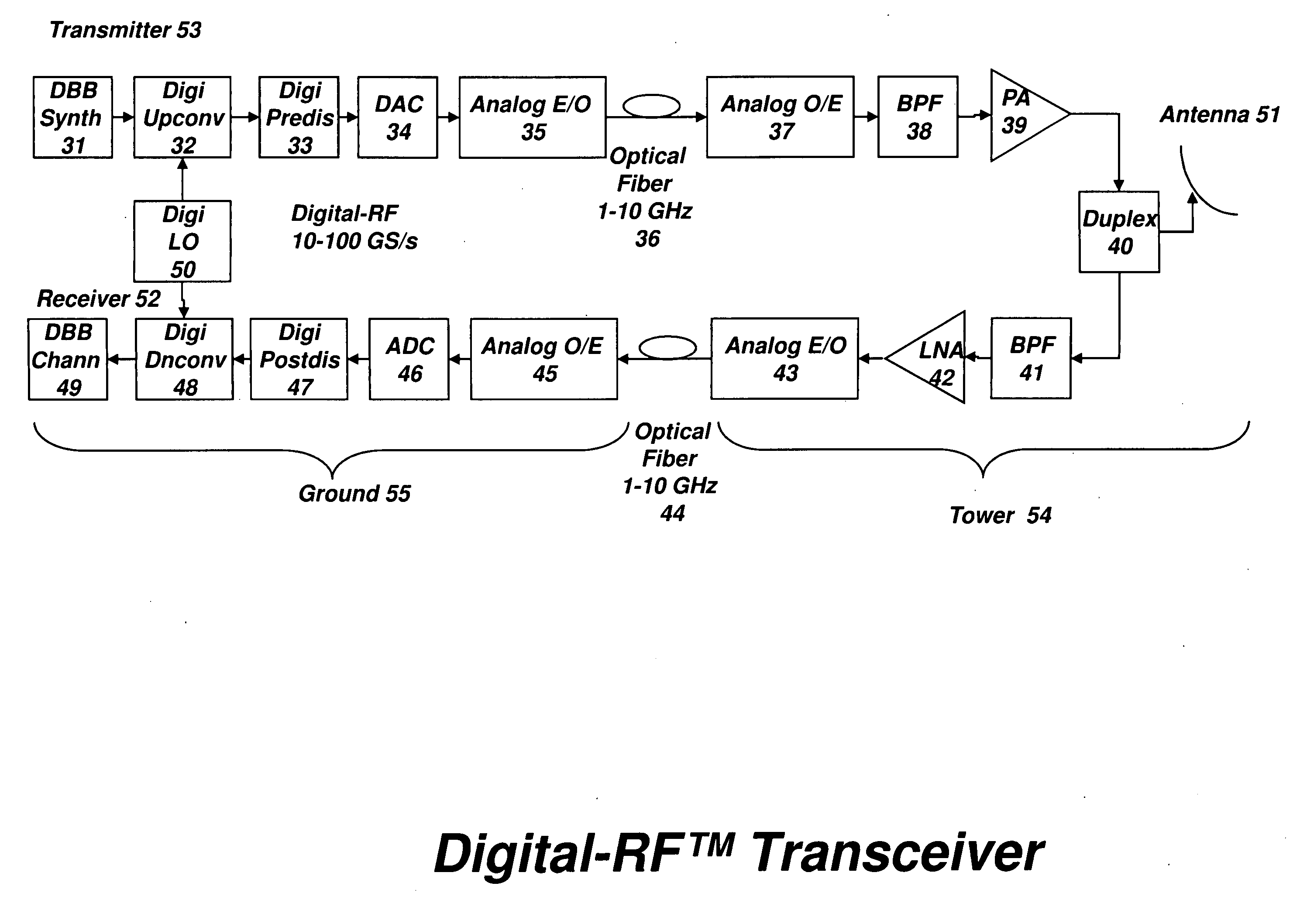
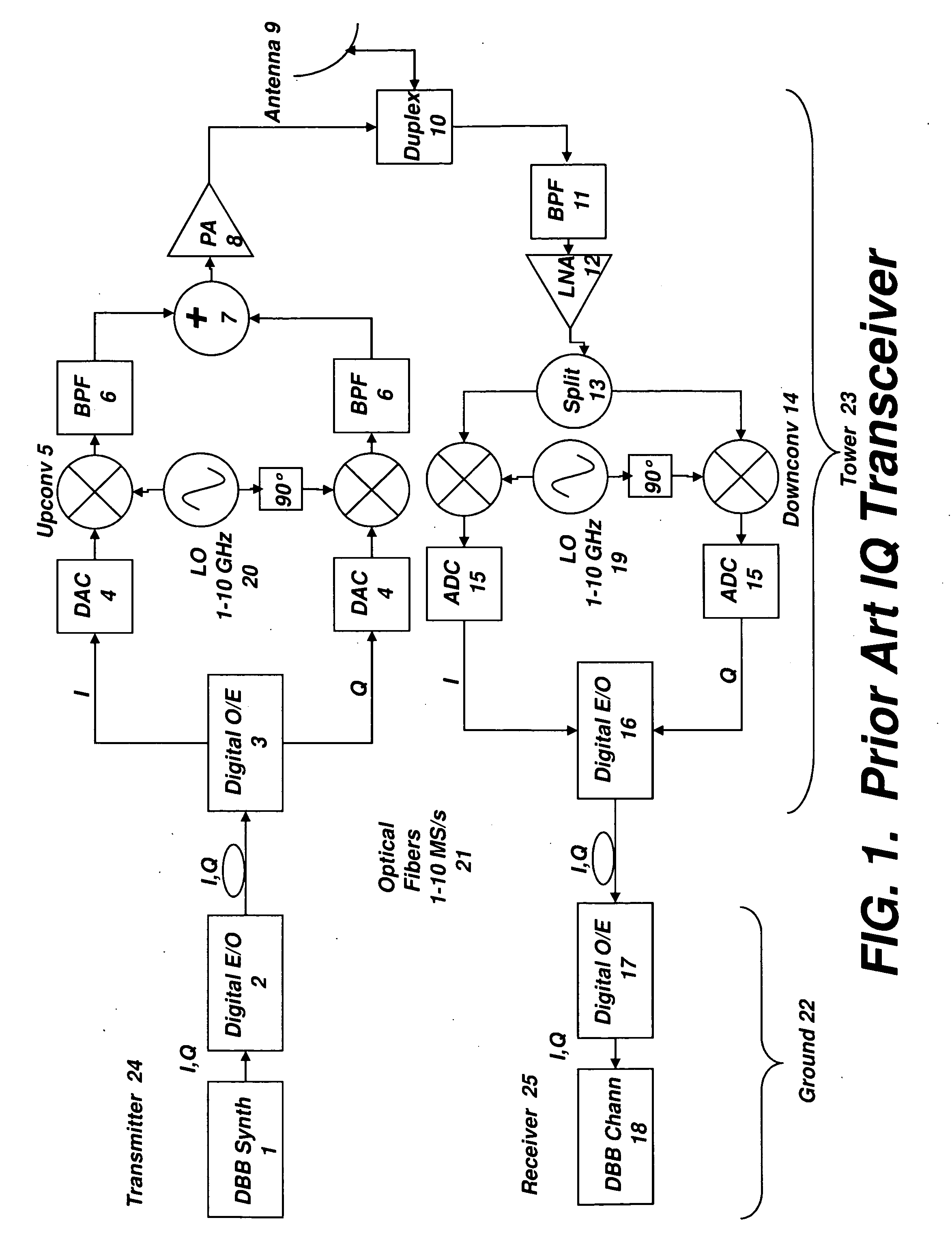
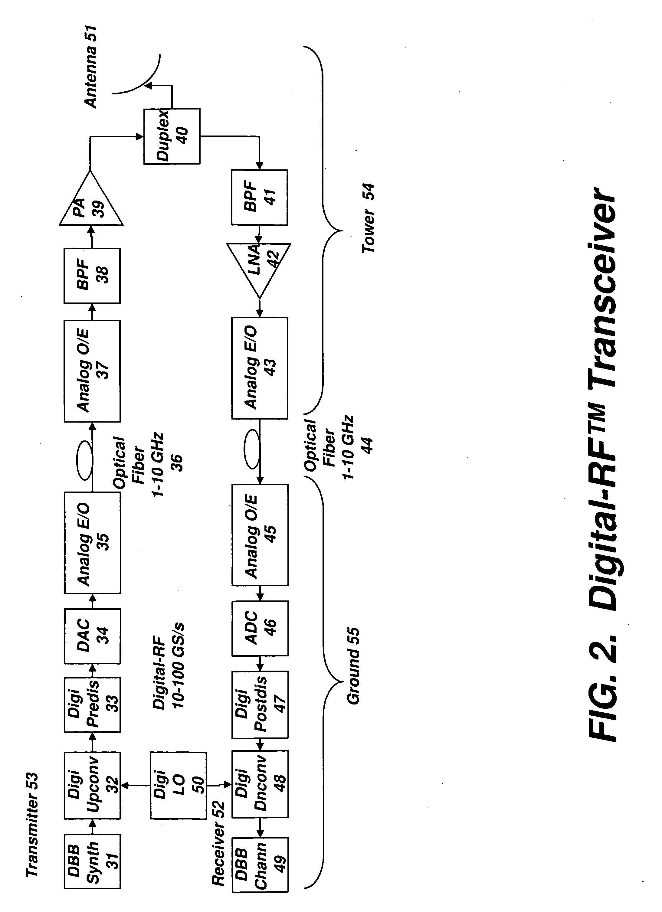
[0099]A block diagram of a modem wireless basestation of the prior art is shown in FIG. 1. This describes a split architecture, which is partitioned into digital baseband (DBB) processing on the ground (i.e., within a base station module) and analog RF processing on the tower. A version of in-phase and quadrature (IQ) receiver and transmitter are shown here, although other variants known in the art may alternatively be applied. Thus, it should be understood that FIG. 1 is simplified, and, for example, portions of the electronics may be duplicated.

[0100]Consider first the transmitter, where the DBB Synthesizer might, for example, generate an OFDM (orthogonal frequency domain multiplexed) signal that is up to a few MHz in bandwidth, comprising many narrow band signals, properly timed and encoded. This digital signal is then used to modulate a diode laser or optical interferometer, and the optical signal is coupled into an optical fiber that is sent up the tower. Optical fibers general...


PUM


Abstract

A transceiver architecture for wireless base stations wherein a broadband radio frequency signal is carried between at least one tower-mounted unit and a ground-based unit via optical fibers, or other non-distortive media, in either digital or analog format. Each tower-mounted unit (for both reception and transmission) has an antenna, analog amplifier and an electro-optical converter. The ground unit has ultrafast data converters and digital frequency translators, as well as signal linearizers, to compensate for nonlinear distortion in the amplifiers and optical links in both directions. In one embodiment of the invention, at least one of the digital data converters, frequency translators, and linearizers includes superconducting elements mounted on a cryocooler.

Description

RELATED APPLICATIONS[0001]The present application claims the benefit of priority of Provisional Patent Application 61 / 035,932, filed, Mar. 12, 2008, the entirety of which is expressly incorporated herein by reference.FIELD OF THE INVENTION[0002]The present invention is directed towards radio-frequency (RF) transceivers, and more specifically towards transceivers that use direct digitization of RF signals, and digital processing thereof.BACKGROUND OF THE INVENTION[0003]A simple RF signal consists of a narrowband baseband signal which is modulated onto a high-frequency RF carrier. A more complex, broader bandwidth RF signal may consist of multiple narrowband signals modulated on similar RF carriers. A conventional RF digital data receiver uses an analog mixer and local oscillator (LO) to translate the signal from the carrier to a lower frequency, the baseband or intermediate frequency (IF), where it is then typically digitized and further signal extraction is performed in the digital ...

Claims


Application Information

Patent Timeline
17 Sep 2009
Publication
US20090232191A1
IPC
H04L27/00; H04B1/40
CPC
H04L27/2096; H04B10/2575; H04B10/697; H04B10/25752; H04B10/40; H04B10/5561
Inventors
GUPTA, DEEPNARAYAN; MUKHANOV, OLEG