
Smart Machining System and Smart Tool Holder Therefor

Inactive Publication Date: 2009-09-17
UNIVERSITY OF NEW HAMPSHIRE
View PDF99 Cites 57 Cited by
  • Summary
  • Abstract
  • Description
  • Claims
  • Application Information

AI Technical Summary

Benefits of technology

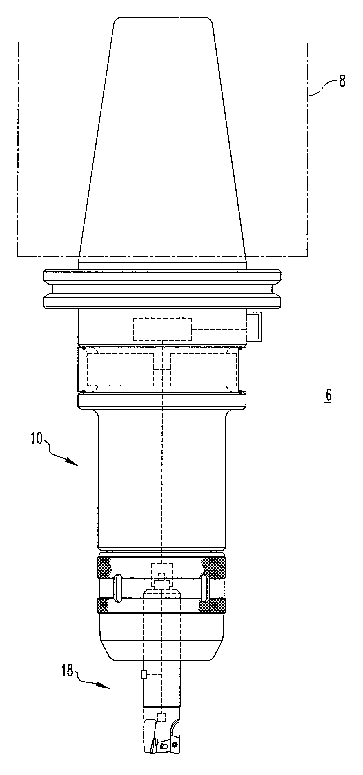
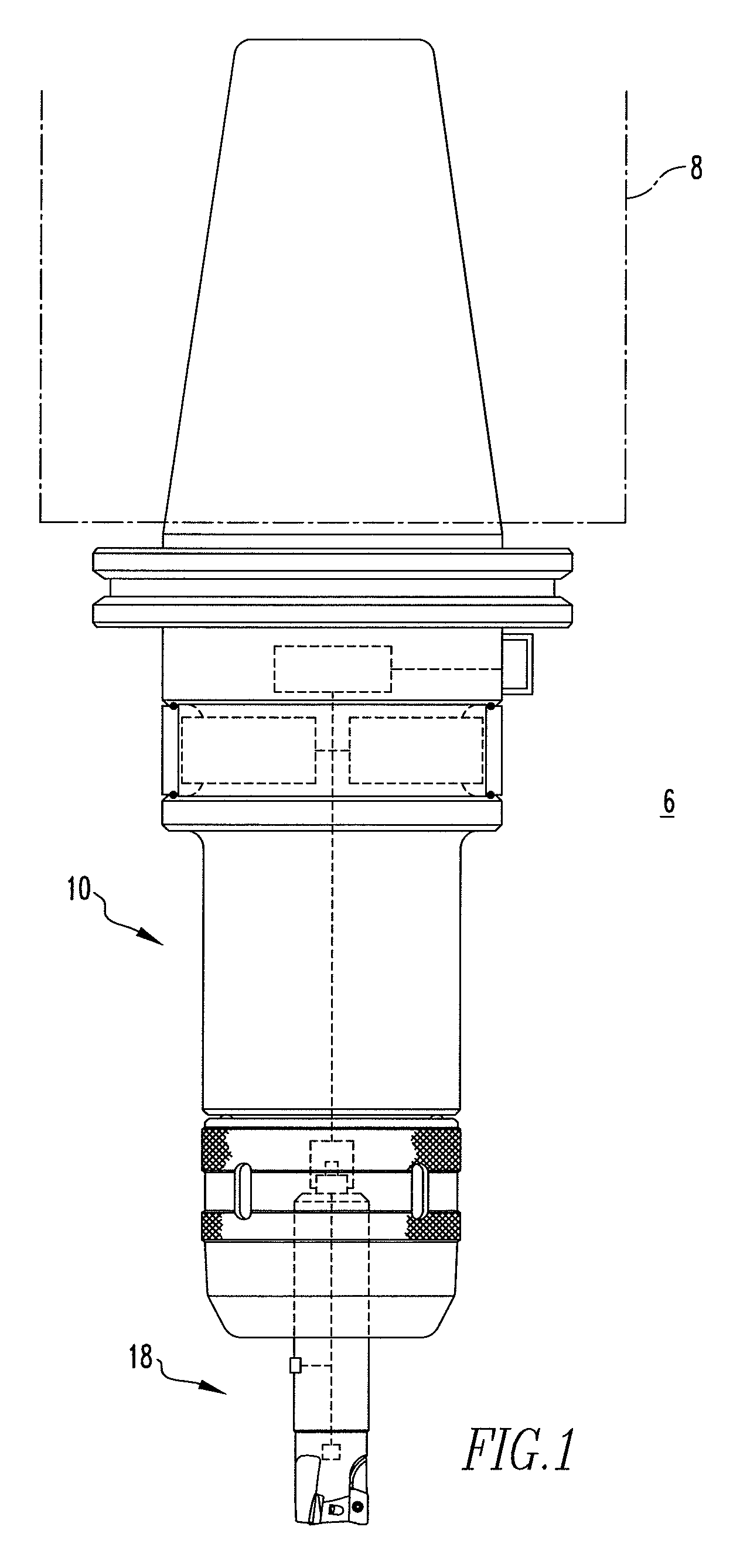
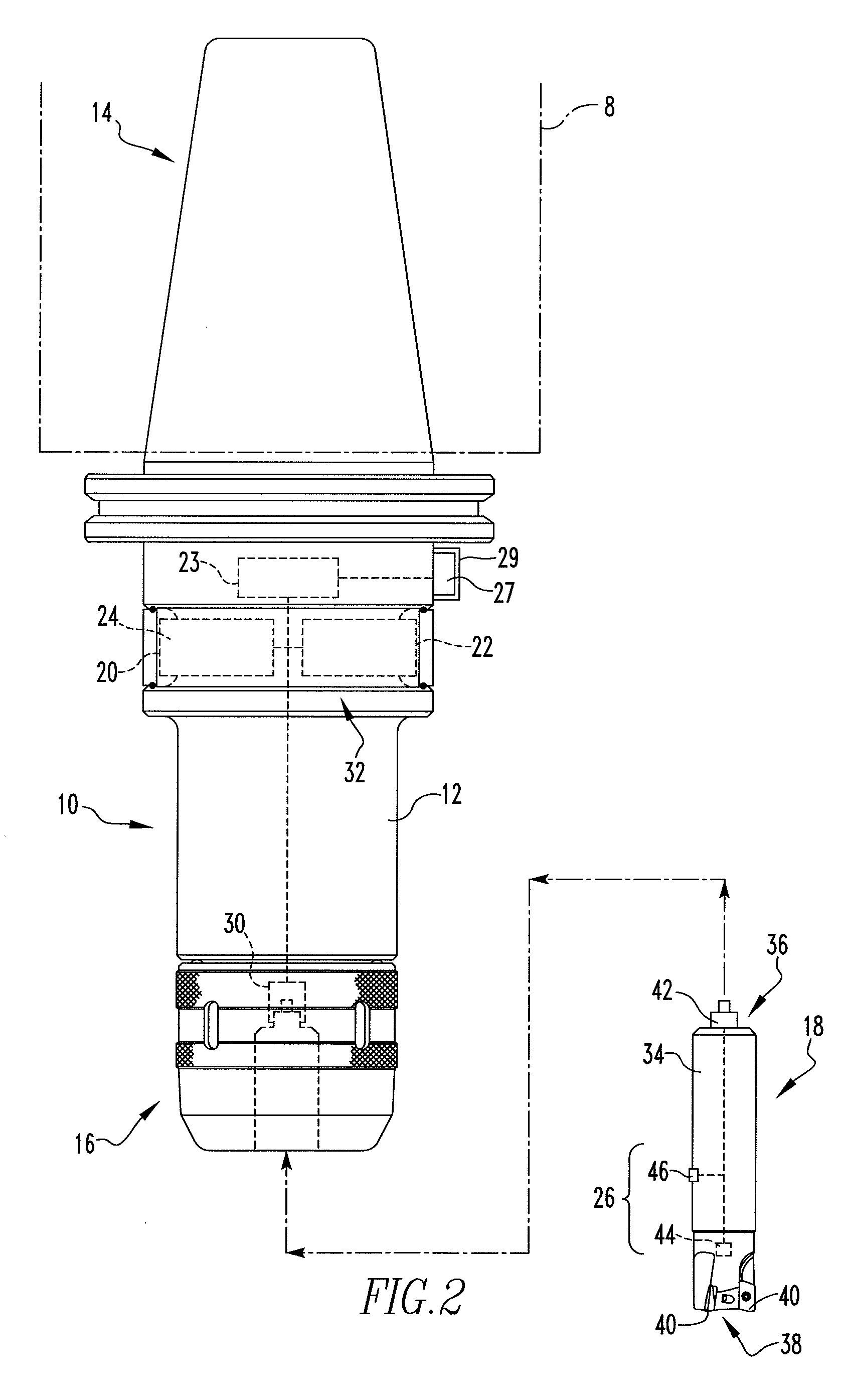
[0017]The opposite second end of the body of the tool holder may comprise a first electrical connector and the first end of the cutting assembly may comprise a second electrical connector, the first electrical connector and the second electrical connector being positioned to cooperatively electrically and mechanically engage when the cutting assembly is coupled to the tool holder thus allowing communication between the number of sensors and the processor.

Problems solved by technology

Unfortunately, many sensor types are high in cost, are invasive to the machining envelope, and / or are difficult to deploy.
Historically, the ability to record in-process data about the response of the tool tip has been limited to data collected from sensors at locations physically distant from the cutting process.
However, the complexity of the end milling system causes noisy transmission of vibration between the tool tip and the location of a traditionally mounted stationary sensor.
This fact increases the difficulty of analyzing the dynamic motion of the tool tip and decreases the resolution on subtle phenomena of interest.
Although non-invasive and cost effective, sensors such as power monitoring do not provide sufficient bandwidth to capture many important details of the machining process.
Additionally, many known condition monitoring techniques require sensors such as bed-type dynamometers which are largely impractical.

Method used


Image

  • Smart Machining System and Smart Tool Holder Therefor
  • Smart Machining System and Smart Tool Holder Therefor
  • Smart Machining System and Smart Tool Holder Therefor

Examples


Embodiment Construction

[0037]As employed herein, the term “number” shall mean one or an integer greater than one (i.e., a plurality).

[0038]As employed herein, the term “processor” means a programmable analog and / or digital device that can store, retrieve, and process data; a computer; a workstation; a personal computer; a microprocessor; a microcontroller; a microcomputer; a central processing unit; a mainframe computer; a mini-computer; a server; a networked processor; or any suitable processing device or apparatus. Example embodiments consists of 8 bit and 32 bit microprocessors with internal DSP (digital signal processing) commands. These processing units are supplemented by high bandwidth digital to analog converters. The processing unit is also supplemented by a specialized coprocessor for controlling digital radio transmission, communication error checking, synchronization with the receiving device, and communications channel operations.

[0039]As employed herein, the term “sensor” means a device or a...


PUM

PropertyMeasurementUnit
Temperatureaaaaaaaaaa
Forceaaaaaaaaaa
Poweraaaaaaaaaa

Abstract

A smart tool holder is for use with a machine tool platform. The smart tool holder includes a body having a first end and an opposite second end, a processor disposed with the body, and a transceiver disposed with the body and in communication with the processor. The transceiver is structured to communicate with an external receiving device. The first end of the body is structured to be coupled to the machine tool platform and the opposite second end is structured to be selectively coupled to a cutting assembly having a number of sensors. The processor is structured to communicate with the number of sensors when the cutting assembly is coupled to the body. The processor may perform data analysis tasks using model based data analysis, digital filtering, and other techniques. The smart tool holder may suggest changes to the machining process based on two-way communication with a machine tool controller through a receiver or interface device.

Description

CROSS-REFERENCE TO RELATED APPLICATION[0001]The present application claims priority from U.S. Provisional Patent Application Ser. No. 61 / 037,033 filed Mar. 17, 2008, the disclosure of which is incorporated herein by reference.BACKGROUND[0002]1. Field of the Invention[0003]The invention relates generally to tool holder assemblies, and, more particularly, to smart tool holders for use with machine tool platforms. The invention also relates to a smart tool assembly for use with a machine tool platform. The invention further relates to a smart machining system employing a smart tool holder.[0004]2. Background Information[0005]Annual U.S. expenditures on machining operations are estimated to be in excess of $200 billion. Accordingly, there exists a great demand for improved cutting tools and machining methods in order to minimize such expenditures. In December 2007, the National Institute of Standards and Technology (NIST) hosted a workshop on “Smart Machine Tools” organized by the Integ...

Claims


Application Information

Patent Timeline
IPC IPC(8): G06F19/00B23B31/00
CPCB23B31/02B23B2231/10B23C5/109Y10T408/94G05B2219/49305Y10T408/21Y10T408/57B23C2260/76
Inventor SUPROCK, CHRISTOPHER A.NICHOLS, JEFFJERARD, ROBERTFUSSELL, BARRY
Owner UNIVERSITY OF NEW HAMPSHIRE
Learn More