Apparatus for carrying out improved control of rotary machine
- Summary
- Abstract
- Description
- Claims
- Application Information
AI Technical Summary
Benefits of technology
Problems solved by technology
Method used
Image
Examples
second embodiment
[0230]A control system according to the second embodiment of the present invention will be described hereinafter with reference to FIG. 6.
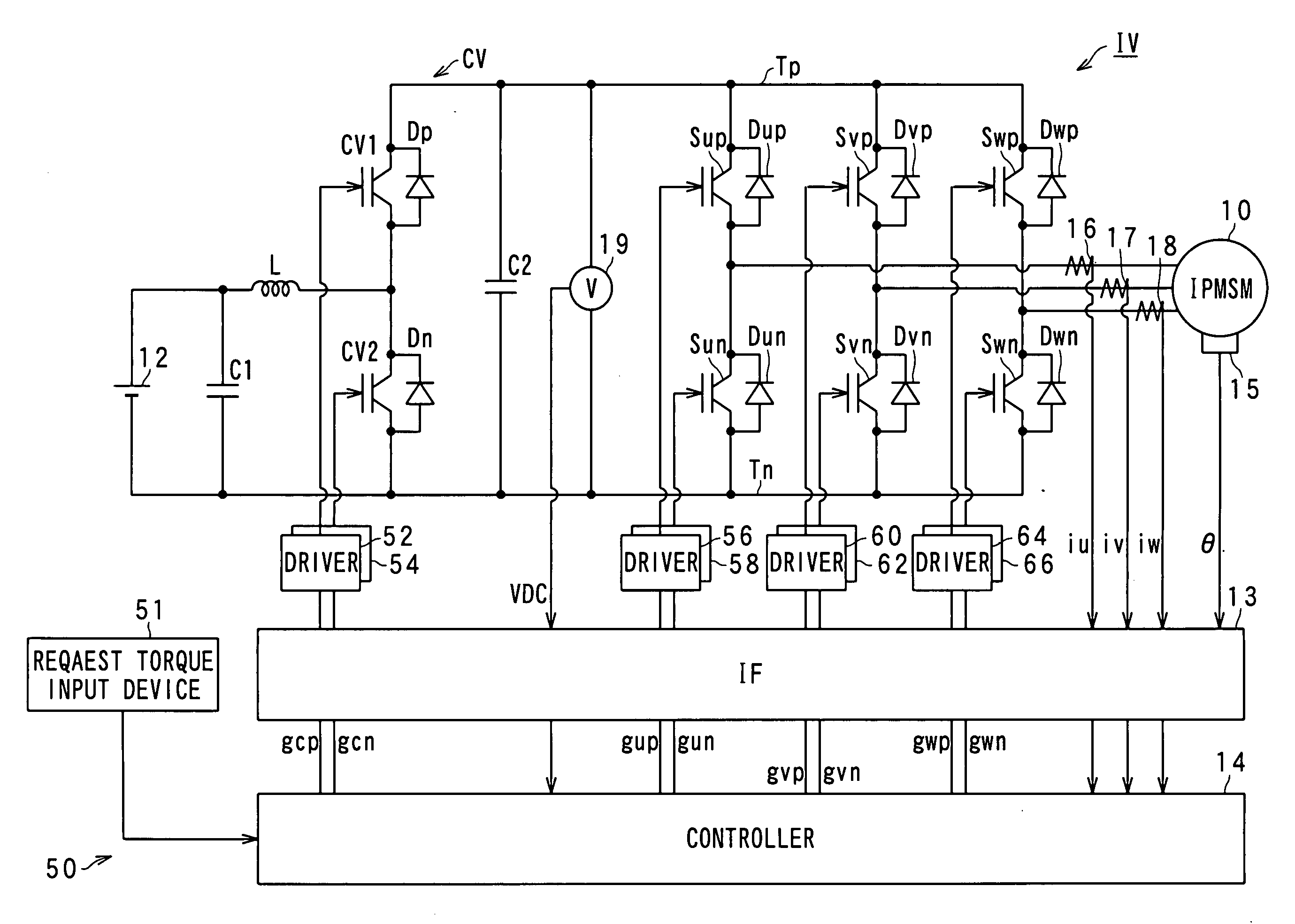
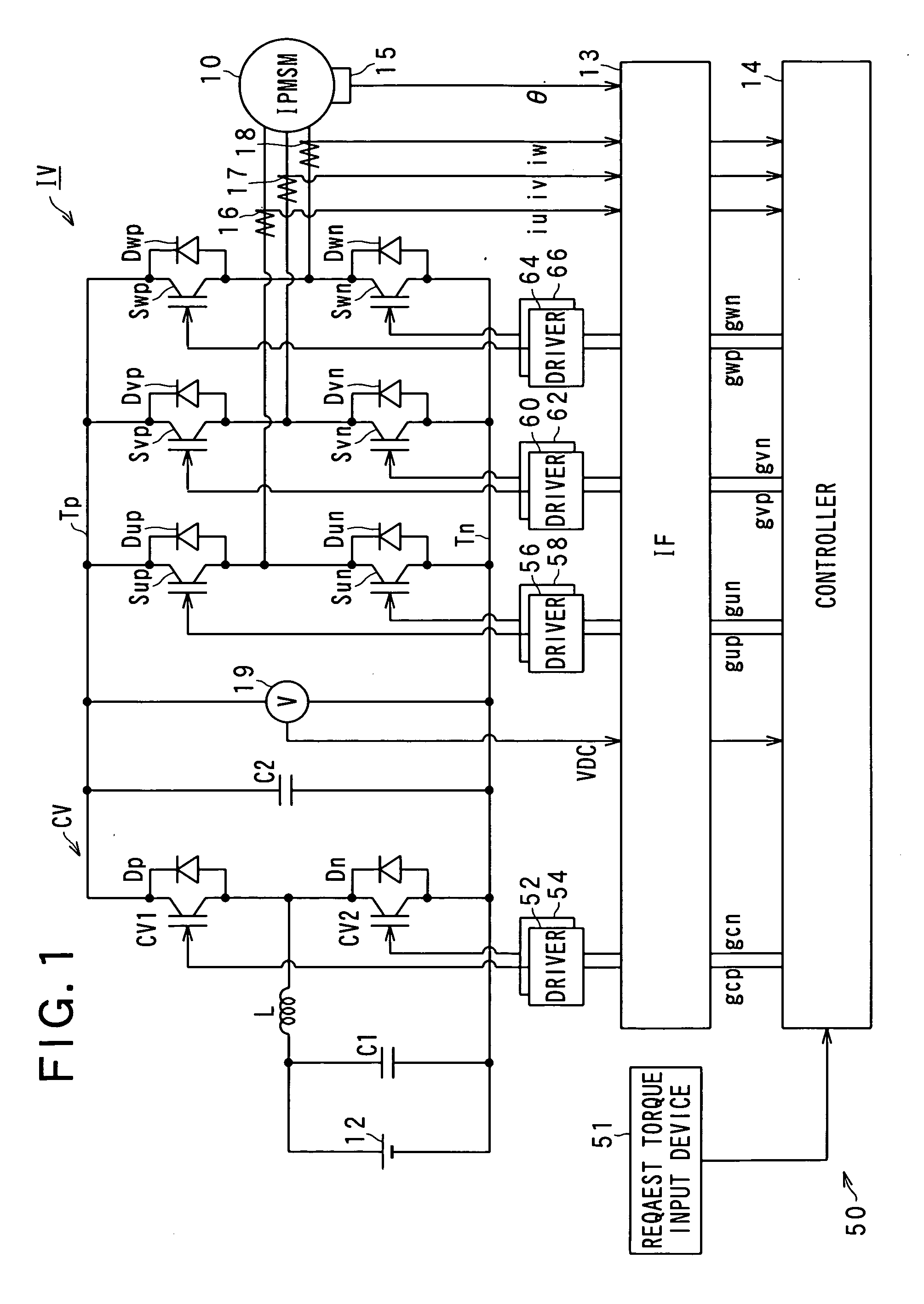
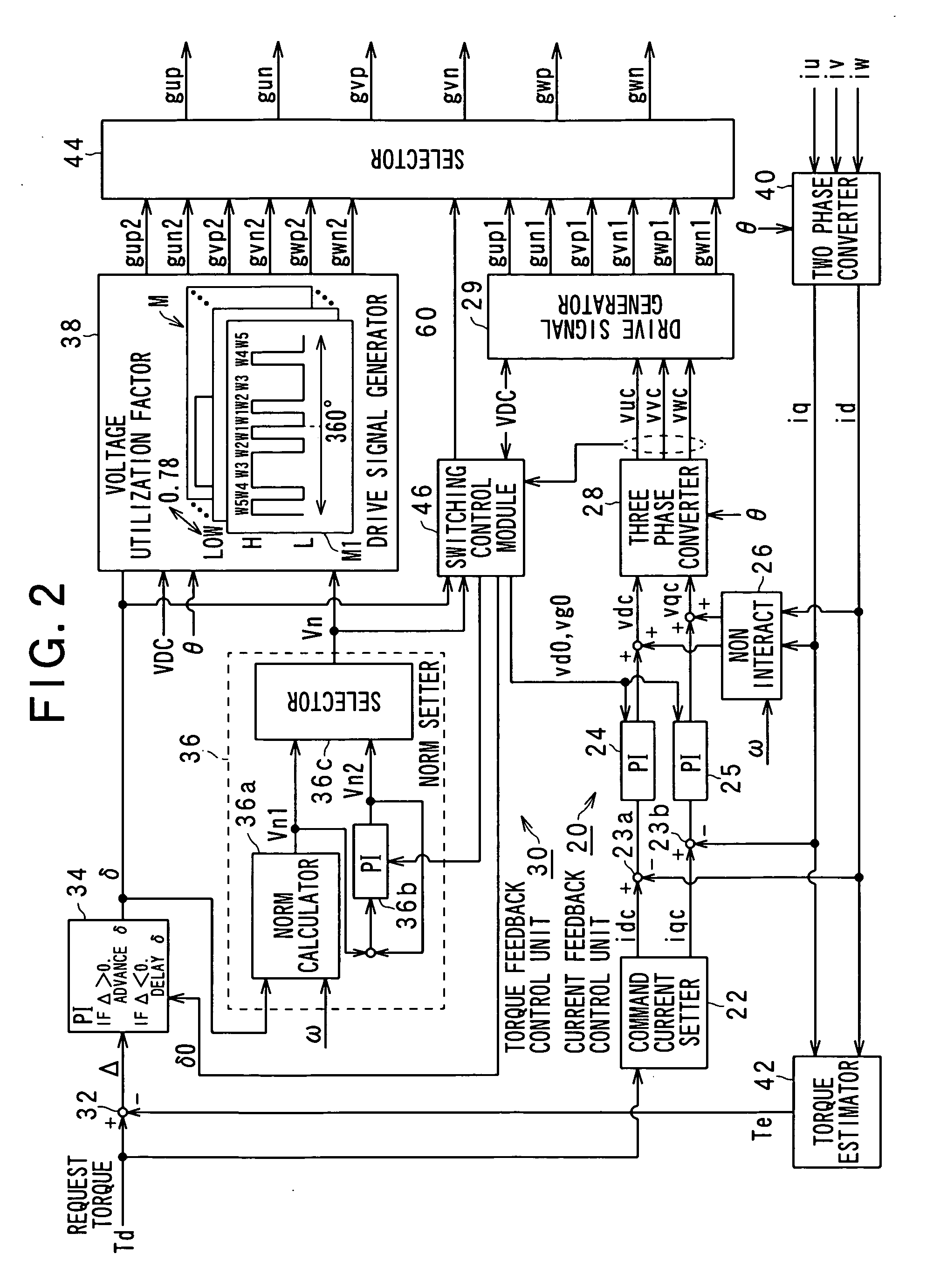
[0231]The structure of the control system according to the second embodiment is substantially identical to that of the control system 50 according to the first embodiment except for the following different points. So, like parts between the control systems according to the first and second embodiments, to which like reference characters are assigned, are omitted or simplified in description.
[0232]FIG. 6 schematically illustrates an example of the functional structure of a norm calculator 36a1 according to the second embodiment.
[0233]Referring to FIG. 6, in the second embodiment, a norm V2 and a phase δ2 of a voltage vector formed by subtracting a portion ωΦ from the vector of the inverter output voltage are defined to represent the torque T, this portion ωΦ is to be cancelled by an induced voltage in the motor-generator 10.
[0234]The norm calculato...
third embodiment
[0239]A control system according to the third embodiment of the present invention will be described hereinafter with reference to FIG. 7.
[0240]The structure of the control system according to the third embodiment is substantially identical to that of the control system 50 according to the first embodiment except for the following different points. So, like parts between the control systems according to the first and third embodiments, to which like reference characters are assigned, are omitted or simplified in description.
[0241]FIG. 7 schematically illustrates an example of the functional structure of a norm calculator 36a2 of the controller 14 upon the control system 50 operating in the power-running mode according to the third embodiment.
[0242]Referring to FIG. 7, in the third embodiment, the norm calculator 36a2 is configured to set the first norm Vn1 such that the d-axis current id becomes zero.
[0243]Specifically, the norm calculator 36a2 is configured to represent the first no...
fourth embodiment
[0248]A control system according to the fourth embodiment of the present invention will be described hereinafter with reference to FIG. 8.
[0249]The structure of the control system according to the fourth embodiment is substantially identical to that of the control system 50 according to the first embodiment except for the following different points. So, like parts between the control systems according to the first and fourth embodiments, to which like reference characters are assigned, are omitted or simplified in description.
[0250]The control system 50 according to the first embodiment is configured not to monitor the actual three-phase alternating currents iu, iv, and iw upon the inverter IV being controlled by the torque-feedback control unit 3. Thus, while the inverter IV is controlled by the torque-feedback control unit 3, when the rotational speed of the motor-generator 10 rapidly falls down, an induced voltage in the motor-generator 10 rapidly falls down. In this case, the th...
PUM
 Abstract
Description
Claims
Application Information
 - R&D
- Intellectual Property
- Life Sciences
- Materials
- Tech Scout
- Unparalleled Data Quality
- Higher Quality Content
- 60% Fewer Hallucinations
Browse by: Latest US Patents, China's latest patents, Technical Efficacy Thesaurus, Application Domain, Technology Topic, Popular Technical Reports.
© 2025 PatSnap. All rights reserved.Legal|Privacy policy|Modern Slavery Act Transparency Statement|Sitemap|About US| Contact US: help@patsnap.com


