Magnetic recording medium and method of manufacturing same

a technology of magnetic recording medium and manufacturing method, which is applied in the field of magnetic recording medium, can solve the problems of difficult stably maintaining perpendicular magnetization, signal overwriting, and prominent appearance of “adjacent track erasure”, and achieve satisfactory surface properties, reduce track edge noise, and improve the effect of magnetic recording quality

Inactive Publication Date: 2009-09-24
FUJI ELECTRIC CO LTD
View PDF17 Cites 21 Cited by
  • Summary
  • Abstract
  • Description
  • Claims
  • Application Information

AI Technical Summary

Benefits of technology

[0015]The provides a magnetic recording medium enabling high-density recording, and a simple method of manufacture of such a magnetic recording medium. Preferably, a magnetic recording medium in accordance with the invention is a perpendicular magnetic recording medium formed by stacking, in order on a nonmagnetic base, at least an underlayer, a magnetic recording layer, and a protective layer, and is characterized in that the magnetic recording layer is formed from at least a plurality of magnetic layers and an exchange-coupling control layer, and in that a physical pattern is formed in the exchange-coupling control layer.
[0017]The coercive force of a signal recording region of the magnetic recording layer can be made smaller than the coercive force of a non-signal recording region. Specifically, a structure can be employed in which an exchange-coupling control layer is used only in signal recording regions of the magnetic recording layer, and moreover the magnetic layers immediately above and immediately below the exchange-coupling control layer are ferromagnetically coupled via the exchange-coupling control layer. That is, by providing an exchange-coupling layer, signal recording regions are low-coercivity regions below the write magnetic field of the head, and non-signal recording regions are high-coercivity regions above the write magnetic field of the head. Further, by controlling the pattern of formation of the exchange-coupling layer, if the signal recording regions are enclosed between non-signal recording regions, then advantages similar to those of the discrete-track medium are effectively obtained. That is, the problem of adjacent track erasure is alleviated, and track edge noise can also be reduced. As a result, track densities can be raised.
[0018]In essence, the difference between the magnetic characteristics of the two regions is brought about by the difference in the film thicknesses of the exchange-coupling layer, and so because there is no disordering of the crystal structure of the coupling layer due to ion implantation or other causes, there is no impediment of epitaxial growth of the magnetic layer formed on the coupling layer. Further, if the film thickness of the exchange-coupling control layer is 2 nm or less, then the surface relief pattern which depends on the exchange-coupling control layer relief pattern is also 2 nm or less, so that satisfactory surface properties are obtained without flattening treatment, that is, head flight stability can be obtained. In other words, a more simple manufacturing method can be provided.

Problems solved by technology

If this energy is smaller than the demagnetizing field energy, it becomes difficult to stably maintain perpendicular magnetization.
However, if ease of writing is increased too much, the problem of “adjacent track erasure” prominently appears.
This is a problem in which the head recording field exerts an effect extending to tracks adjacent to the track which is originally to be recorded, so that signals are overwritten, that is, erased.
The anisotropy magnetic field of the backing layer is increased, and this tends to sacrifice ease of writing.
However, methods to fabricate such media are more complex than in the prior art.
That is, raising the track density becomes difficult.
On the other hand, in the case of discrete media proposed in the past such as in Japanese Patent Laid-open No. 9-97419 (corresponding to U.S. Pat. No. 6,014,296), the method of manufacture is attended by major problems.
However, when CMP (chemical-mechanical polishing) is used for flattening, this problem becomes particularly prominent, whereas when dry etching is employed, comparatively uniform machining is possible, but long lengths of time are required, posing problems from the standpoint of manufacturing.
And, when using ion implantation methods such as in Japanese Patent Laid-open No. 2002-288813 and in Japanese translation of PCT application No. 2003-536199, flattening techniques are not necessary, but it is difficult to control the spreading of implanted ions, the effect of backscattering, and other factors.
In particular, when using the method employing ion implantation into a coupling layer of Japanese translation of PCT application No. 2003-536199, the effect of backscattering causes changes in the magnetic characteristics of the magnetic layer immediately below, and this means degradation of the characteristics of the recording layer which is crucial for information recording.
In addition, the crystal structure in the coupling layer is disordered, so that there is the drawback that epitaxial growth of another magnetic layer formed directly above is impeded.
This also means that the functions of the recording layer are degraded.
However, in Japanese translation of PCT application No. 2003-536199, in addition to the problem with manufacturing described above, because the recording method is an in-plane recording method, there is a problem from the standpoint of higher densities.

Method used


Image

  • Magnetic recording medium and method of manufacturing same
  • Magnetic recording medium and method of manufacturing same
  • Magnetic recording medium and method of manufacturing same

Examples


example 1

PRACTICAL EXAMPLE 1

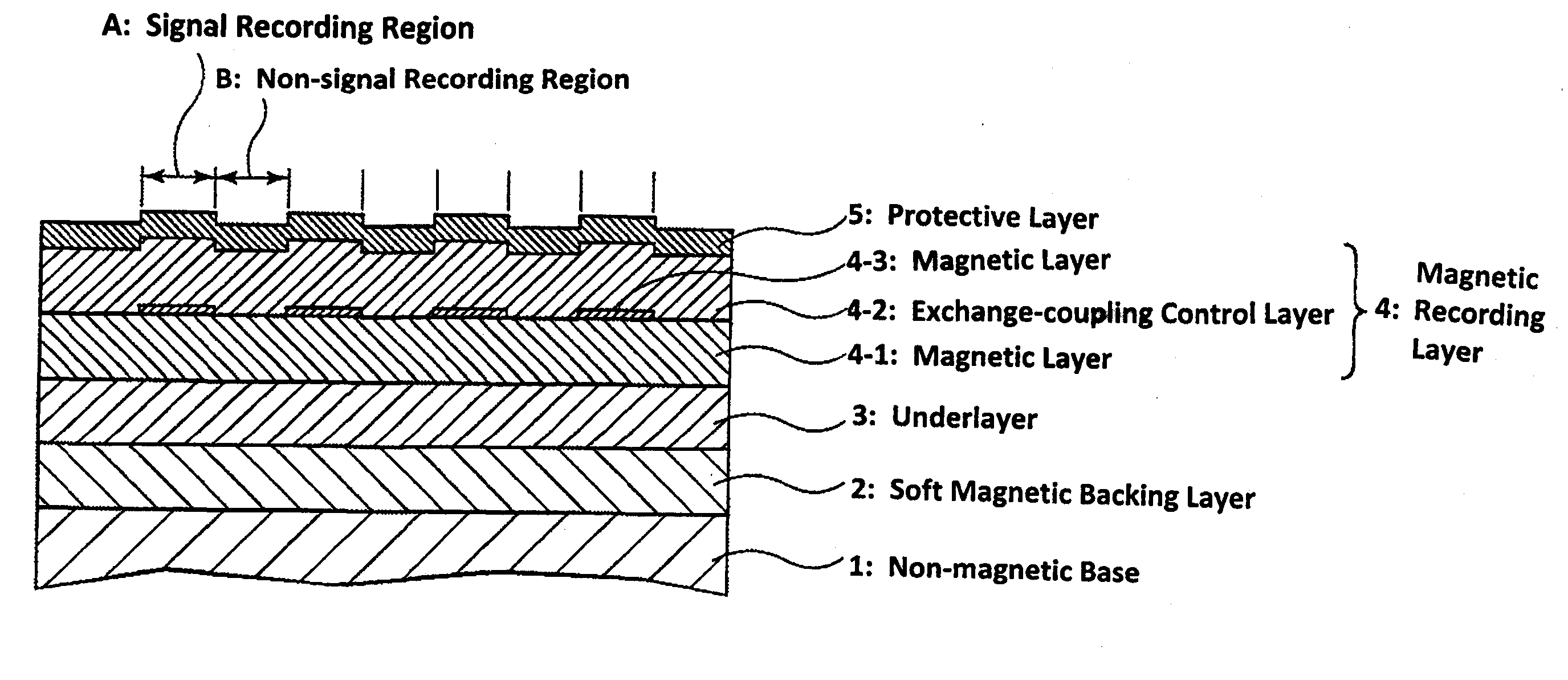
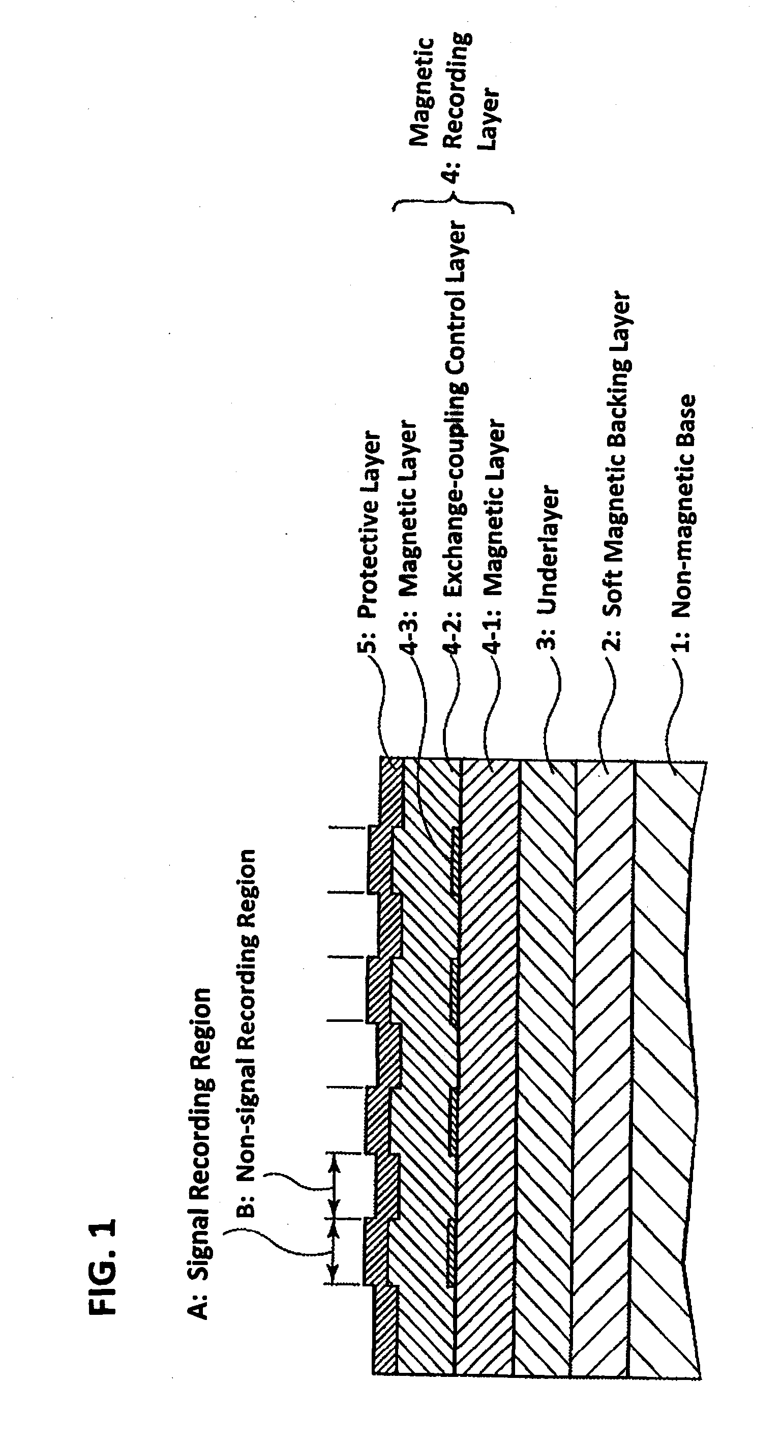
[0049]As the nonmagnetic base 1, a disc-shape glass substrate with a flat surface was used; after cleaning, the substrate was placed in a sputtering chamber, and a Co88Nb7Zr5 target was used to form a CoNbZr film 80 nm thick at an Ar gas pressure of 5 mTorr, to form the CoNbZr soft magnetic backing layer 2.

[0050]Next, a Ru target was used to deposit a Ru underlayer 3 of thickness 20 nm by sputtering at an Ar gas pressure of 30 mTorr. Then, a (CO70Pt20Cr10)94(SiO2)6 target was used to form a CoPtCr—SiO2 layer (magnetic layer 4-1) to a thickness of 8 nm at an Ar gas pressure of 60 mTorr. Then, a mask pattern disc, in which a mask pattern was formed, was placed between substrate and sputtering target, and a Ru target was used at an Ar gas pressure of 30 mTorr to form a Ru layer to 0.25 nm as the exchange-coupling control layer 4-2 only in regions which were to serve as signal recording regions A.

[0051]Next, a CO71Cr20Pt5B4 target was used to form a CoCrPtB layer (mag...


PUM

PropertyMeasurementUnit
thicknessaaaaaaaaaa
thicknessaaaaaaaaaa
thicknessaaaaaaaaaa

Abstract

A magnetic recording medium is formed by stacking in order, on a nonmagnetic base, at least an underlayer, magnetic recording layer, and protective layer. The magnetic recording layer includes a plurality of magnetic layers and an exchange-coupling control layer, and the magnetic recording medium is characterized in that a physical pattern is formed in the exchange-coupling control layer. The exchange-coupling control layer is located between the magnetic layers of the magnetic recording layer.

Description

BACKGROUND[0001]The present invention relates to a magnetic recording medium and to a method of manufacturing the same. The magnetic recording medium is installed in various magnetic recording devices.[0002]Perpendicular magnetic recording methods, which have been studied for many years as technology to achieve high recording densities in magnetic recording, have recently been commercialized. In such methods, the recording magnetization is made perpendicular to the plane of the recording medium; henceforth perpendicular magnetic recording is expected to replace conventional longitudinal recording methods, in which the recording magnetization is parallel to the plane. A perpendicular magnetic recording medium (or more concisely, perpendicular medium) used in perpendicular magnetic recording mainly comprises a magnetic recording layer of a hard magnetic material; an underlayer to orient the recording magnetization in the magnetic recording layer in the perpendicular direction; a prote...

Claims


Application Information

Patent Timeline
Patent Type & Authority Applications(United States)
IPC IPC(8): G11B5/66G11B5/84
CPCG11B5/66
Inventor WATANABE, SADAYUKI
Owner FUJI ELECTRIC CO LTD
Why Eureka
Try Eureka