
Electrochemical energy cell system

a technology of electrochemical energy and cell system, applied in the direction of non-aqueous electrolyte cells, cell components, sustainable manufacturing/processing, etc., can solve the problems of reducing capacity, increasing the probability of failure, and disadvantages of prior electrochemical energy systems for standby applications, so as to maintain system availability

Inactive Publication Date: 2009-09-24
PRIMUS POWER CORP
View PDF0 Cites 38 Cited by
  • Summary
  • Abstract
  • Description
  • Claims
  • Application Information

AI Technical Summary

Benefits of technology

[0008]complexity and inefficiency of requiring active cooling systems during discharge, which can further reduce capacity;
[0013]mal-distribution of zinc metal from internal shunt currents between cells of differing potential further reduces available capacity;
[0014]a long length of small diameter channels required for minimizing shunt currents during operation further reduce system capacity due to pumping losses;

Problems solved by technology

There are certain weaknesses or disadvantages in prior electrochemical energy systems for standby applications.
These include, but are not limited to, the following:an inability to store sufficient energy without requirement to charge the system, precluding availability while in a discharged condition;complexity and inefficiency of requiring active cooling systems during discharge, which can further reduce capacity;ambiguities in diagnosing symptoms of failure, which can significantly increase a probability of failure; andhydrogen generation, which can be a significant and costly safety issue.
Specific weaknesses or disadvantages in prior metal halogen systems for standby applications also include, but are not limited to, the following:inability to maintain a state of readiness without significant capacity loss due to self-discharge;mal-distribution of zinc metal from internal shunt currents between cells of differing potential further reduces available capacity;a long length of small diameter channels required for minimizing shunt currents during operation further reduce system capacity due to pumping losses;metallic dendritic growth during the charge mode can permanently damage a metal halogen system and lead to premature and hazardous failure conditions.

Method used


Image

  • Electrochemical energy cell system
  • Electrochemical energy cell system
  • Electrochemical energy cell system

Examples


Embodiment Construction

Electrolyte Energy Cell System

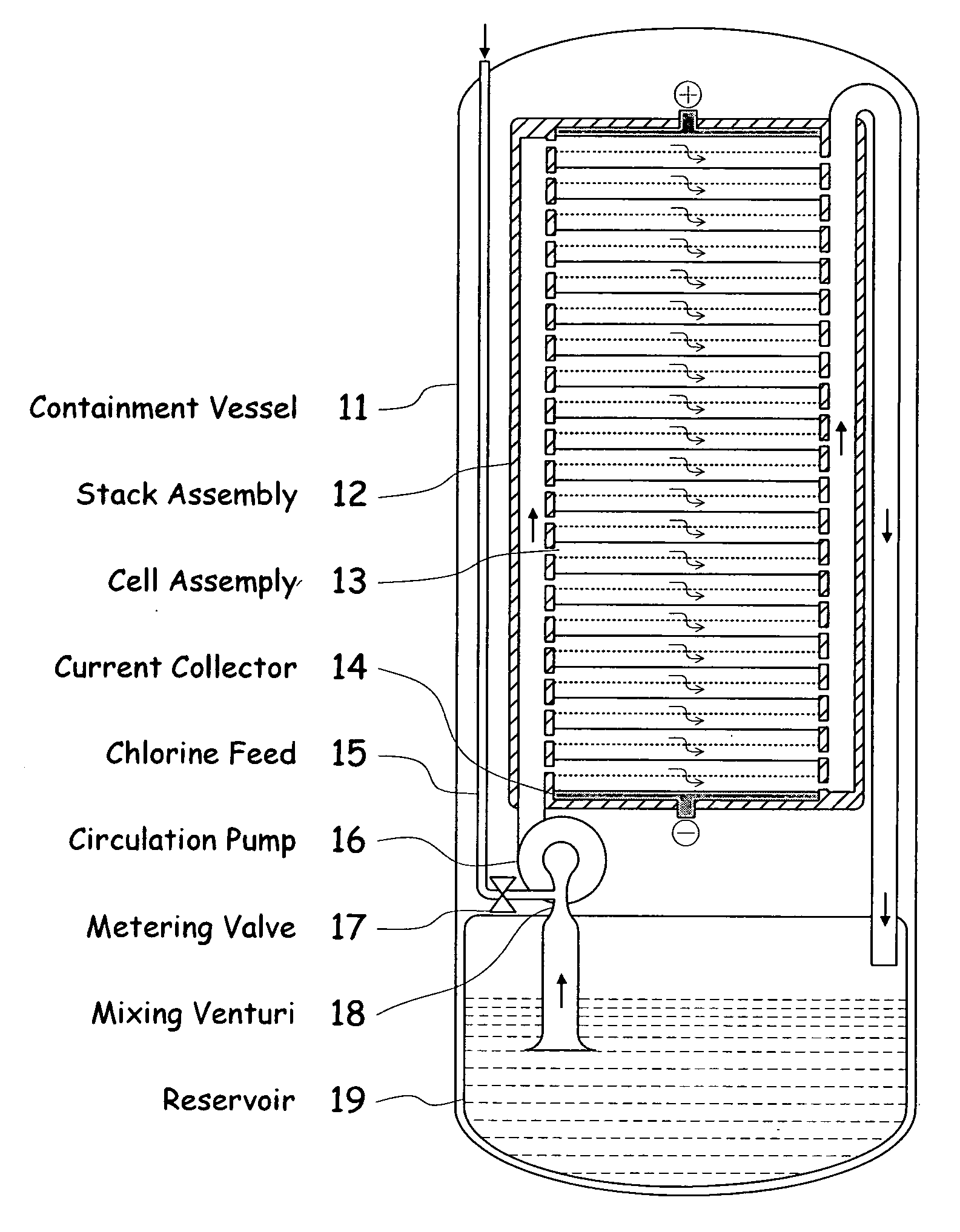
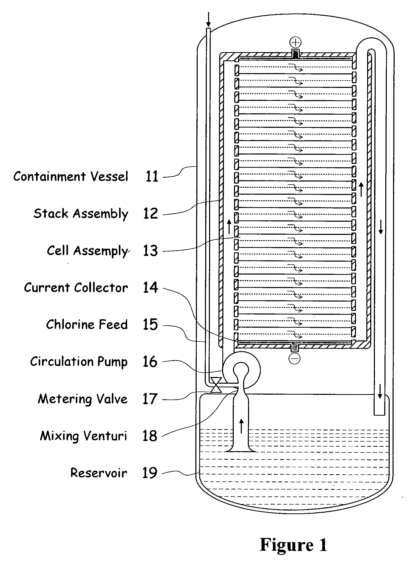
[0039]FIG. 1 illustrates a metal halogen electrochemical energy cell system according to the invention.

[0040]One embodiment of the invention that attempts to address some or all of these weaknesses and disadvantages is a metal halogen electrochemical energy cell system. This embodiment includes at least at least one positive and at least one negative electrode, a reaction zone between the positive electrode and the negative electrode, at least one electrolyte that includes a metal and a halogen, and a circulation pump that conveys the electrolyte through the reaction zone. The electrolyte and a halogen reactant can be mixed before, at, or after the pump, for example using a mixing venture. Preferably, the positive electrode is made of porous carbonaceous material, the negative electrode is made of zinc, the metal include zinc, the halogen includes chlorine, the electrolyte includes an aqueous zinc-chloride electrolyte, and the halogen reactant includes ...


PUM


Abstract

A metal halogen electrochemical energy cell system that generates an electrical potential. One embodiment of the system includes at least one cell including at least one positive electrode and at least one negative electrode, at least one electrolyte, a mixing venturi that mixes the electrolyte with a halogen reactant, and a circulation pump that conveys the electrolyte mixed with the halogen reactant through the positive electrode and across the metal electrode. Preferably, the negative electrodes are made of zinc, the metal is zinc, the positive electrodes are made of porous carbonaceous material, the halogen is chlorine, the electrolyte is an aqueous zinc-chloride electrolyte, and the halogen reactant is a chlorine reactant. Also, variations of the system and a method of operation for the systems.

Description

BACKGROUND OF THE INVENTION[0001]1. Field of the Invention[0002]The present invention relates to metal halogen electrochemical energy systems.[0003]2. Related Art[0004]One type of electrochemical energy system uses a halogen component for reduction at a normally positive electrode, and an oxidizable metal adapted to become oxidized at a normally negative electrode during the normal dispatch of the electrochemical system. An aqueous electrolyte is used to replenish the supply of halogen component as it becomes reduced at the positive electrode. The electrolyte contains the dissolved ions of the oxidized metal and reduced halogen and is circulated between the electrode area and a reservoir area and an elemental halogen injection and mixing area, to be consumed at the positive electrode. One example of such a system uses zinc and chlorine system.[0005]Such electrochemical energy systems are described in prior patents including U.S. Pat. Nos. 3,713,888, 3,993,502, 4,001,036, 4,072,540, ...

Claims


Application Information

Patent Timeline
IPC IPC(8): H01M6/04H01M2/38H01M50/574H01M50/77
CPCH01M2/025H01M10/0472H01M2/34H01M2/40H01M4/42H01M4/8605H01M4/96H01M12/04H01M12/085H01M2300/0002Y02E60/50H01M8/04186H01M8/08H01M10/0413H01M2/12Y02E60/10H01M50/77Y02P70/50H01M50/574H01M50/138H01M50/30
Inventor WINTER, RICHARD OTTO
Owner PRIMUS POWER CORP
Learn More