Interconnector line of thin film, sputter target for forming the wiring film and electronic component using the same

a technology of interconnectors and thin films, applied in the direction of vacuum evaporation coatings, semiconductor/solid-state device details, coatings, etc., can solve the problems of sputtering adverse effects in the subsequent process, and color of the ito electrode, so as to prevent the effective electrochemical reaction with the ito or the like, suppress the occurrence of dust in the sputtering, and prevent the effect of hillocks

Inactive Publication Date: 2015-04-21
KK TOSHIBA
View PDF32 Cites 2 Cited by
  • Summary
  • Abstract
  • Description
  • Claims
  • Application Information

AI Technical Summary

Benefits of technology

[0022]Thus, by finely and uniformly precipitating the intermetallic compound, intermetallic compound forming element and high electrode potential electrode, the etching property is improved extensively, and the occurrence of dust in sputtering can be suppressed. And, at least one type of element selected from the added C, O, N and H does not cause an adverse effect on the effect of suppressing the diffusion of Al or the effect of suppressing the electrochemical reaction with ITO or the like. Therefore, the occurrence of hillocks can be prevented effectively by the intermetallic compound-forming element. Otherwise, the electrochemical reaction with the ITO or the like can be prevented effectively by the high electrode potential element.
[0023]As described above, the first interconnector line of thin film of the invention excels in hillock resistance and formability of a fine interconnector line network. And, the second interconnector line of thin film of the invention excels in preventing property of the electrochemical reaction with the ITO or the like and formability of the fine interconnector line network. The interconnector line of thin film of the invention can concurrently have such properties.

Problems solved by technology

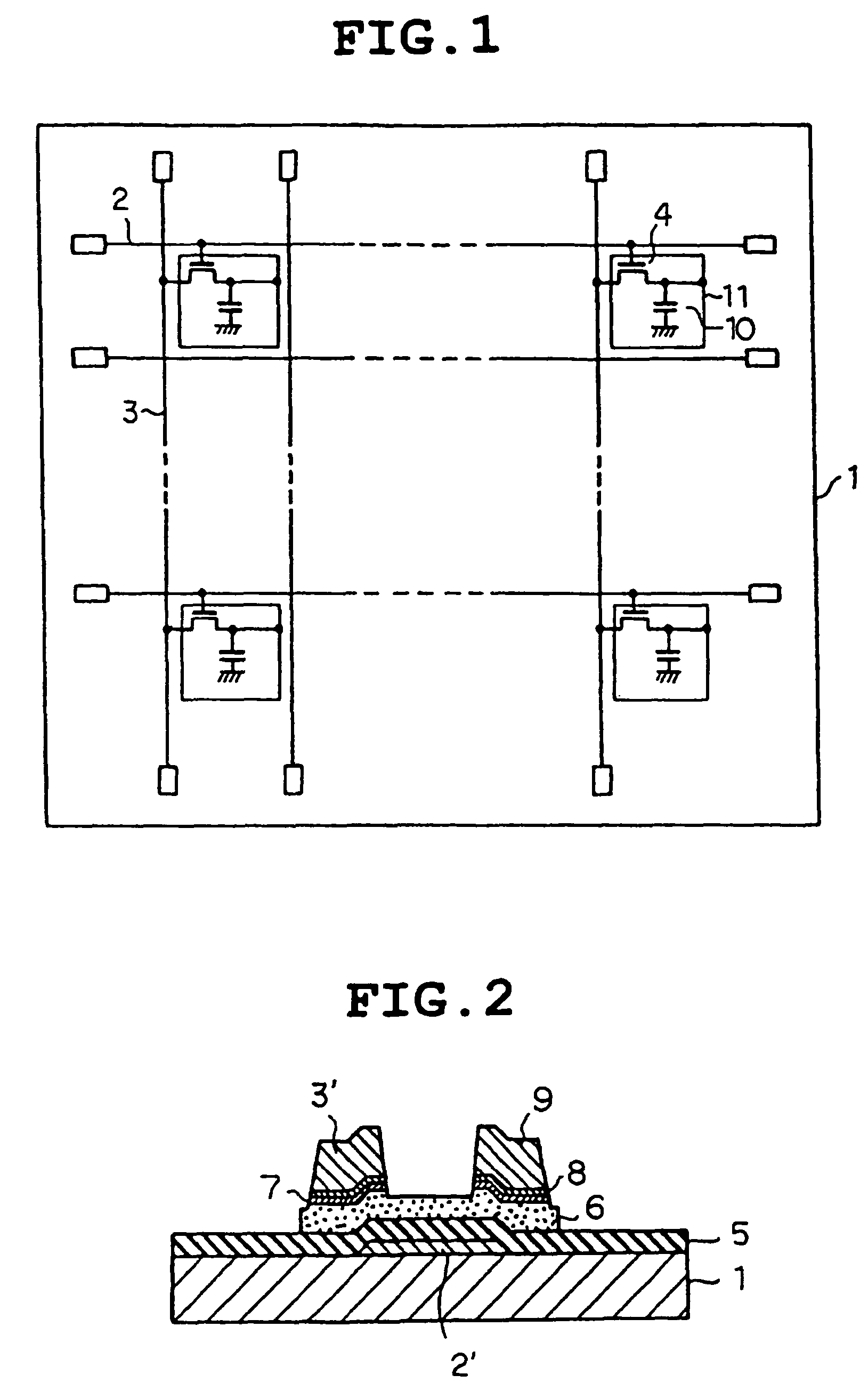
With the Al interconnector line of thin film, low-resistance interconnector line can be achieved, but the Al interconnector line of thin film has a problem of having protrusions called hillocks due to heating at about 473 to 773K by a heat treatment and a CVD process after interconnector line.
When the protrusions are formed on the Al interconnector line, an adverse effect is caused in the subsequent process.
Electrons are moved between the Al interconnector line and the ITO electrode due to the electrochemical reaction, resulting in a problem that the ITO electrode is colored (e.g., blackening) by being reduced and the Al interconnector line is conversely oxidized to lower electrical characteristics.
However, the above-described Al interconnector line of thin film containing a very small amount of metallic elements suppress the diffusion of Al and the electrochemical reaction with the ITO electrode, but there are problems that the produced intermetallic compound and the added metallic elements cause an adverse effect on the etching property and sputtering property of the Al interconnector line.
Specifically, when dry etching such as CDE (chemical dry etching) and RIE (reactive ion etching) or wet etching is made on the above-described Al interconnector line of thin film, a lot of undissolved remains called residues are produced, causing a serious difficulty in forming an interconnector line network.
And, the Al target containing the metallic elements described above causes a large amount of dust while sputtering, causing a difficulty in forming a good and fine interconnector line network.
But, such a stacked film involves a complex LCD structure and a high cost, so that it is desired to suppress the electrochemical reaction with the ITO electrode by the Al interconnector line having a single layered structure.
For example, where the Al interconnector line is applied to a typical semiconductor device such as VLSI and ULSI, electromigration is a problem.
Hei 4-48854), but there is a problem that residues are caused in etching and dust is caused in sputtering as in the case of the LCD.
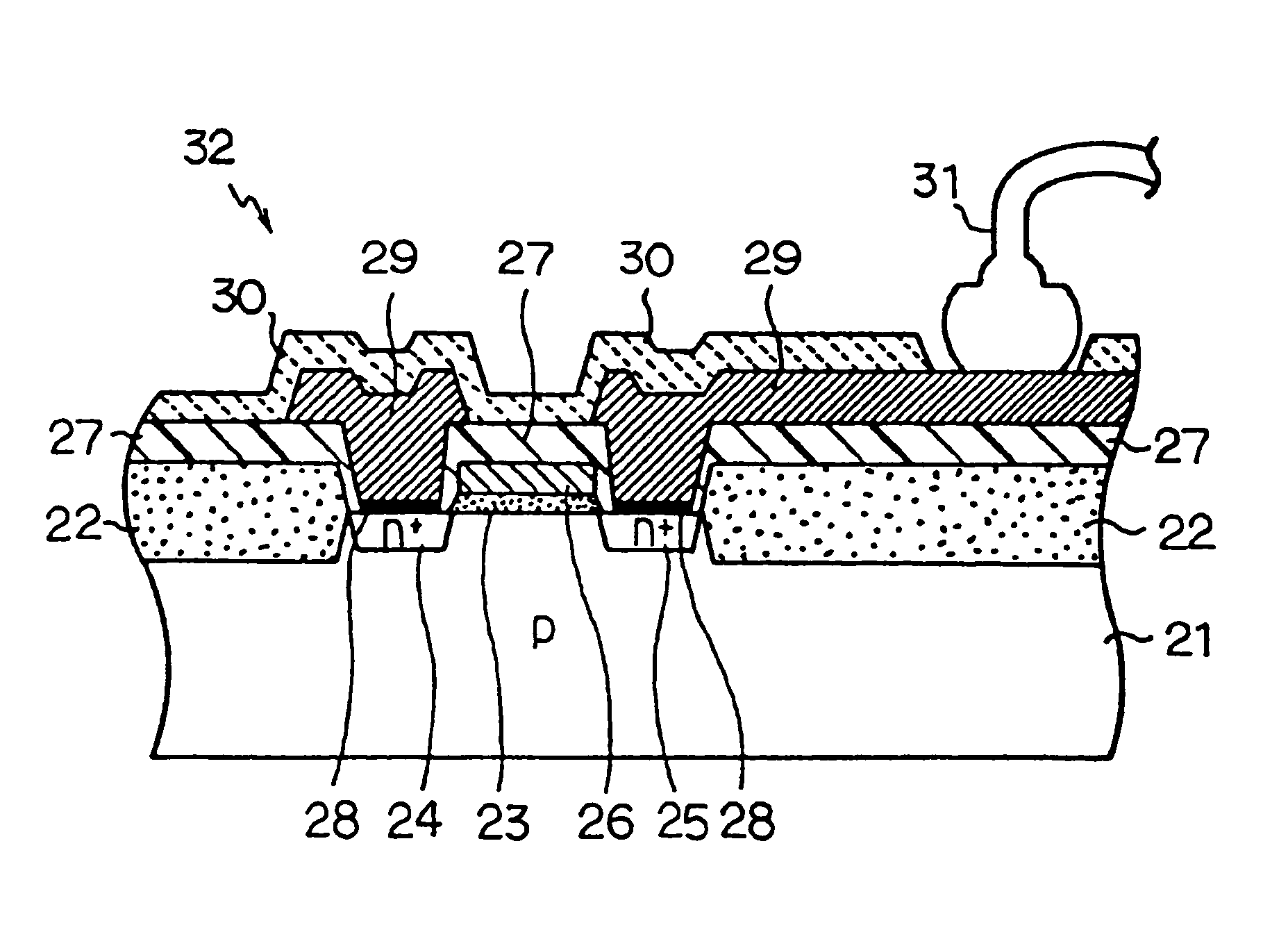
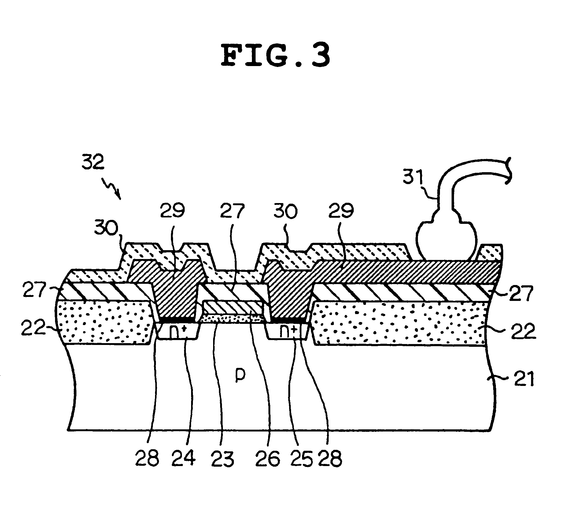
And, the above-described subject is also an issue in a surface acoustic wave apparatus such as a surface acoustic wave oscillator (SAW), an electronic part using SAW (SAW device), or interconnector line and electrodes for a thermal printer head (TPH).

Method used


Image

  • Interconnector line of thin film, sputter target for forming the wiring film and electronic component using the same
  • Interconnector line of thin film, sputter target for forming the wiring film and electronic component using the same
  • Interconnector line of thin film, sputter target for forming the wiring film and electronic component using the same

Examples


example 1

[0078]First, 0.83 at % (2.7 wt %) of Y with respect to Al and 1630 at ppm (220 wt ppm) of C with respect to Y were added to Al, and this mixed material was undergone high-frequency melting to produce an ingot having a target composition. Cold rolling and machining were performed on this ingot to produce an Al sputter target having a diameter of 127 mm and a thickness of 5 mm.

[0079]Using the Al sputter target obtained as described above, an Al film having a thickness of 350 nm was formed by spin precipitation on a glass substrate having a diameter of 5 inches under conditions of a back pressure of 1×10⁻⁴ Pa, power of 200W DC and sputter time of 3 min. The Al film was measured to evaluate on a specific resistance, a hillock density after the heat treatment (573 K) and the presence or not of etching residue. Etching for an evaluation test of the etching residue was performed using. a BCl3+Cl2 mixture gas as etching gas. The results are shown in Table 1.

[0080]And, as comparative example...

example 2

[0083]After producing the Al sputter targets having respective compositions shown in Table 2 in the same way as in Example 1, sputtering was performed under the same conditions as in Example 1 to produce respective Al interconnector line of thin films. These Al interconnector line of thin films were measured to evaluate their properties in the same way as in Example 1. The results are also shown in Table 2.

[0084]

TABLE 2Target compositionEvaluated properties ofAmount ofAl sputter filmintermetallic HillockcompoundAmountSpecificdensityformingof C *1resis-after heatEtchingSampleelements(atomictancetreatmentresidueNo.(atomic ratio)ratio)(μΩ cm)*2*3Example 21Al-071% Y5%3.5◯Non2Al-0.73% Y12%3.8⊚Non3Al-1.1% Y200 ppm4.1⊚Non4Al-1.73% Y580 ppm4.6⊚Non5Al-1.2% Y7%5.1⊚Non6Al-2.83% Y90 ppm6.3⊚Non7Al-4% Y37.8%6.7⊚Non8Al-2% Y300 ppm5.1⊚Non9Al-1.8% Y1.8 ppm4.9◯NonComparative example 21Al-2.3% YNon4.5⊚Yes2Al-4% Y55% 4.9⊚Yes

example 3

[0085]After producing Al targets using various types of elements instead of Y (compositions shown in Table 3) in the same way as in Example 1, respective Al interconnector line of thin films were obtained by sputtering under the same conditions as in Example 1.

[0086]These Al interconnector line of thin films were measured to evaluate their properties in the same way as in Example 1. And, the Al interconnector line of thin films of sample Nos. 16 through 21 were measured to evaluate reactivity with the ITO electrode in an alkaline solution. Reactivity with the ITO electrode in the alkaline solution was examined by a generally used electrode measuring method using silver / silver chloride electrodes as a reference electrode and ITO as the anode and respective Al alloys as the cathode. The results are also shown in Table 3.

[0087]

TABLE 3Target compositionEvaluated properties of AlAmount ofsputter elements (atomic ratio)intermetallicHillockEtch-Reac-SamplecompoundAmountSpecificdensityingti...


PUM

PropertyMeasurementUnit
thicknessaaaaaaaaaa
diameteraaaaaaaaaa
diameteraaaaaaaaaa

Abstract

An interconnector line of thin film comprising 0.001 to 30 at % of at least one kind of a first element capable of constituting an intermetallic compound of aluminum and/or having a higher standard electrode potential than aluminum, for example, at least one kind of the first element selected from Y, Sc, La, Ce, Nd, Sm, Gd, Tb, Dy, Er, Th, Sr, Ti, Zr, V, Nb, Ta, Cr, Mo, W, Mn, Tc, Re, Fe, Co, Ni, Pd, Ir, Pt, Cu, Ag, Au, Cd, Si, Pb and B; and one kind of a second element selected from C, O, N and H in a proportion of 0.01 at ppm to 50 at % of the first element, with the balance comprising substantially Al. In addition to having low resistance, such an Al interconnector line of thin film can prevent the occurrence of hillocks and the electrochemical reaction with an ITO electrode. The interconnector line of thin film can be obtained by sputtering in a dust-free manner by using a sputter target having a similar composition.

Description

CROSS-REFERENCE TO RELATED APPLICATIONS[0001]More than one reissue application has been filed for the reissue of U.S. Pat. No. 6,329,275; the reissue applications include reissue application Ser. No. 10 / 732,888, filed on Dec. 10, 2003, the present reissue application Ser. No. 11 / 386,117, filed on Mar. 22, 2006, which is a continuation of reissue application Ser. No. 10 / 732,888, now U.S. Pat. No. Re. 41,975 and reissue application Ser. Nos. 11 / 386,114, 11 / 386,115, and 11 / 386,116, each filed on Mar. 22, 2006, which are also continuations of reissue application Ser. No. 10 / 732,888. These reissue applications claim the benefit of priority under 35 U.S.C. §119 to Japanese Patent Application No. 7-264472, which was filed in the Japanese Patent Office on Oct. 12, 1995.TECHNICAL FIELD[0002]The invention relates to an interconnector line of thin film suitable for forming low-resistance interconnector line, a sputter target for forming an interconnector line of thin film and electronic parts ...

Claims


Application Information

Patent Timeline
Patent Type & Authority Patents(United States)
IPC IPC(8): H01L21/20C22C21/00
CPCC22C21/00C22C1/026C22F1/04C23C14/3414C23C14/14C22C1/0416B22F3/10B22F3/14B22F3/15C22C1/047
Inventor ISHIGAMI, TAKASHIWATANABE, KOICHINITTA, AKIHISAMAKI, TOSHIHIROYAGI, NORIAKI
Owner KK TOSHIBA
Why Eureka
Try Eureka