
Low Pressure Mixing System for Desalting Hydrocarbons

Inactive Publication Date: 2009-10-01
CAMERON SOLUTIONS
View PDF15 Cites 5 Cited by
  • Summary
  • Abstract
  • Description
  • Claims
  • Application Information

AI Technical Summary

Benefits of technology

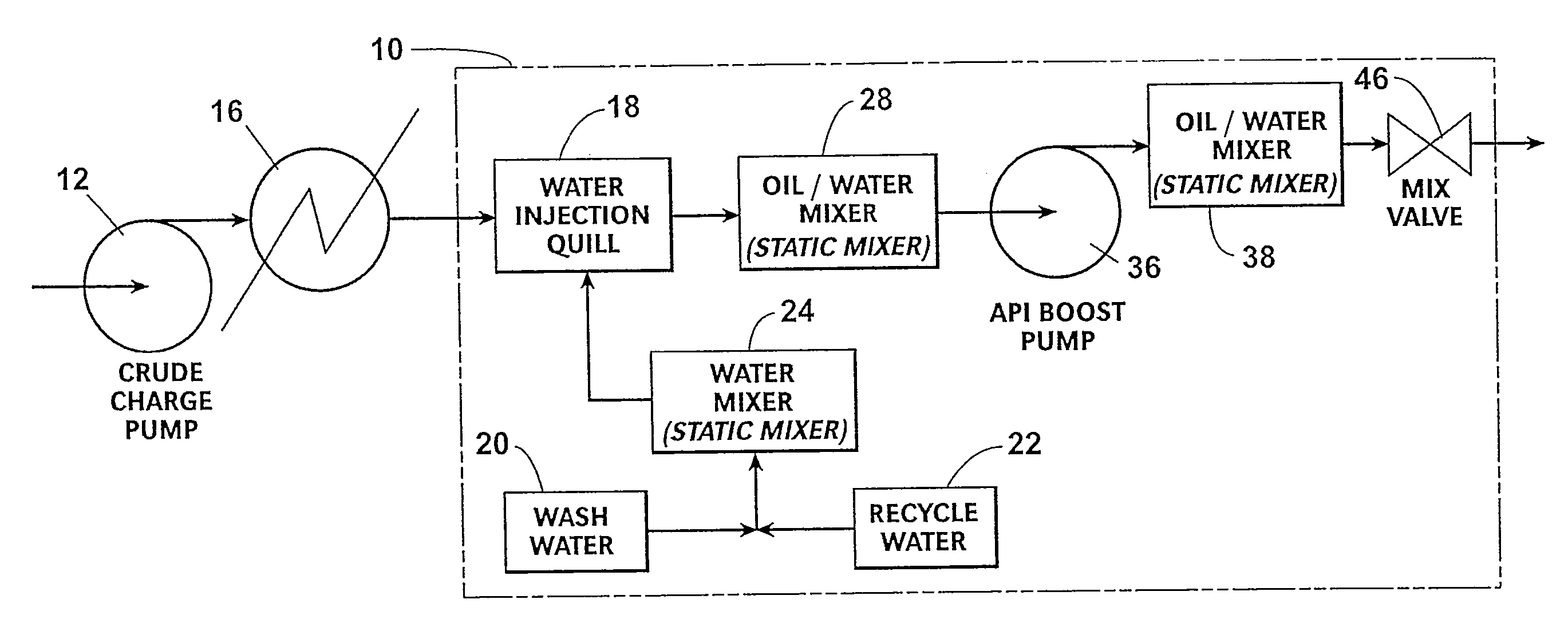
[0007]A method and system for reducing the salt content of a crude oil stream includes using a quill to disperse a fresh water stream into the crude oil stream and then routing the mixed oil / water stream through four mixing stages. Each mixing stage increases the homogeneity of the mixed oil / water stream. The first mixing stage produces the only backpressure the crude charge pump needs to overcome. Upon exiting the fourth stage, the mixed oil / water stream is electrostatically treated in a separator vessel. The separator vessel may be a dual frequency separator vessel or a dual polarity separator vessel (desalter). The desalted oil is removed from an upper portion of the vessel and the effluent water is extracted from a lower portion of the vessel.

Problems solved by technology

Because these crystals cannot be removed directly by the electrostatic process, the crystals must first be dissolved or wetted by the fresh water.
However, the crystals are difficult to dissolve because they are oil-coated.
A second, more common problem occurs in refineries where salt levels must be reduced to very low levels in order to avoid corrosion and catalyst fouling.
Although the oil arriving at a refinery has been previously processed by a production company to meet a refinery acceptance specification, residual water containing salt remains as a very fine dispersion and is very difficult to remove.
This back pressure reduces the capacity of the pump, thereby affecting the crude charge rate.
The data support a finding that higher mixer energy is required to dissolve salt crystals but at the same time it creates an emulsion that is more difficult to resolve.

Method used


Image

  • Low Pressure Mixing System for Desalting Hydrocarbons
  • Low Pressure Mixing System for Desalting Hydrocarbons
  • Low Pressure Mixing System for Desalting Hydrocarbons

Examples


Embodiment Construction

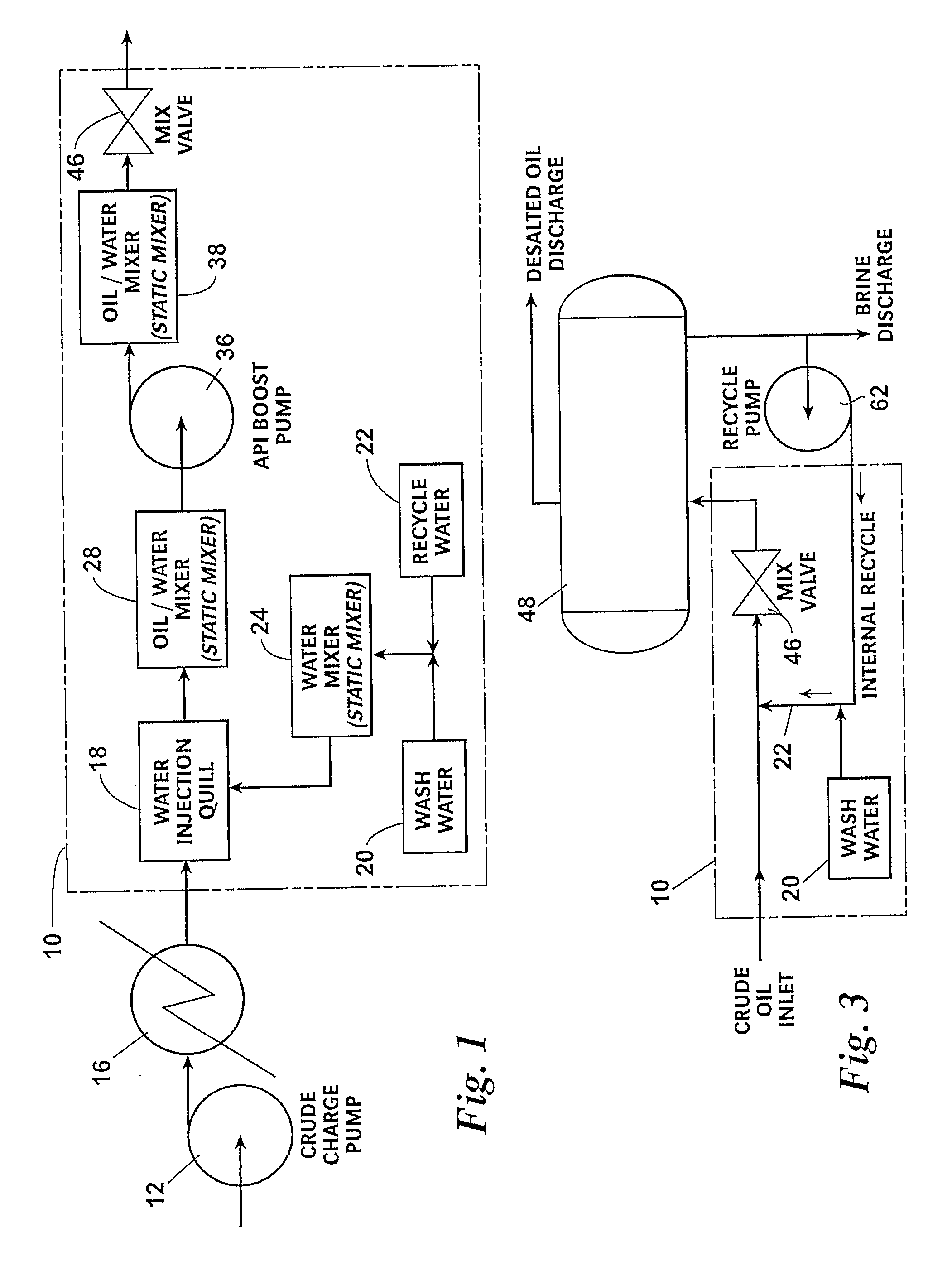
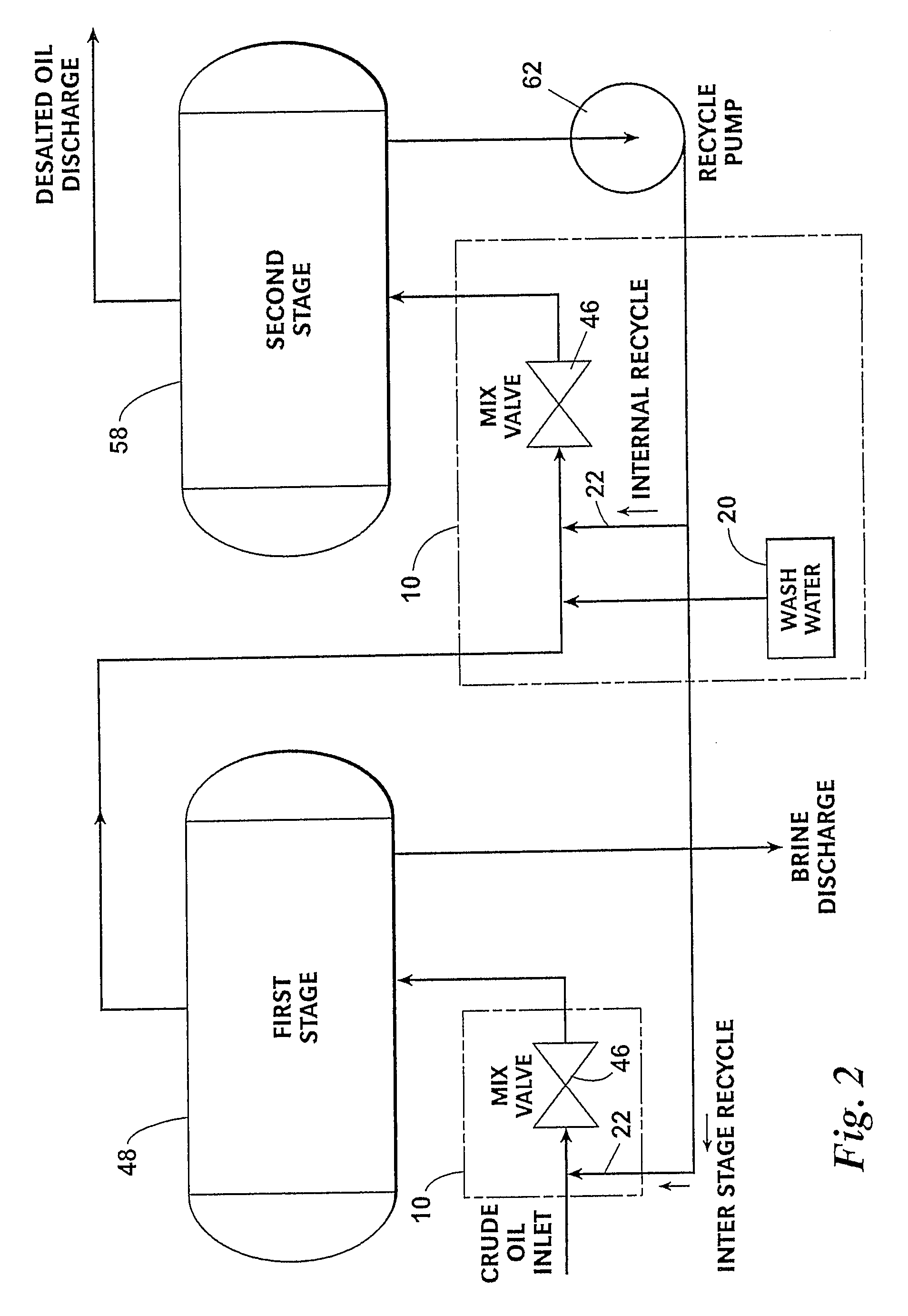
[0015]The invention described below is not limited in its application to the details illustrated in the accompanying drawings. The invention is capable of other embodiments and of being practiced or carried out in a variety of ways. The phraseology and terminology employed herein are for purposes of description and not limitation. Elements illustrated in the drawings are identified by the following numbers:

[0016]10 Oil / water mix system

[0017]12 Crude charge pump

[0018]16 Heat Exchanger

[0019]18 Quill

[0020]20 Wash water

[0021]22 Recycled water

[0022]24 Water static mixer

[0023]26 Isolation valve

[0024]28 Oil / water static mixer

[0025]30 Pressure gauge

[0026]32 Bypass valve

[0027]34 Pressure gauge

[0028]36 API boost pump

[0029]38 Oil / water static mixer

[0030]40 Isolation valve

[0031]42 Pressure gauge

[0032]46 Mix valve

[0033]48 Separator vessel

[0034]50 Isolation valve

[0035]52 Isolation valve

[0036]58 Separator vessel

[0037]62 Recycle pump

[0038]64 Bypass piping

[0039]Referring to the drawings and first to...


PUM

PropertyMeasurementUnit
Pressureaaaaaaaaaa
Pressureaaaaaaaaaa
Pressureaaaaaaaaaa

Abstract

A method and system for reducing the salt content of a crude oil stream includes using a quill to disperse a water stream into the crude oil and then routing the mixed oil / water stream through a plurality of mixing stages. The water stream may include a wash water that has been preconditioned with recycled effluent water. Each mixing stage increases the homogeneity of the mixed oil / water stream. The first and third mixing stages are preferably lower pressure stages relative to the second mixing stage, which provides pressure effective for flowing the mixed oil / water stream through the third and fourth mixing stages. Upon exiting the fourth mixing stage, the mixed oil / water stream is electrostatically treated in a dual frequency separator vessel or a dual polarity separator vessel.

Description

CROSS-REFERENCE[0001]This application claims priority to, and the benefit of, U.S. Provisional Patent Application No. 61 / 039,897, filed on Mar. 27, 2008.BACKGROUND OF THE INVENTION[0002]The typical process for desalting crude oil involves mixing fresh water into a crude oil stream and taking a pressure drop across a mixing valve. In this way the fresh water “washes” the salt out of the oil. Once the oil and water are mixed, the water is extracted from the oil by flowing the mixture through an electrostatic dehydrator. To avoid creating an emulsion that an electrostatic field cannot process, the pressure drop across the mixing valve is typically limited to less than 15 psi.[0003]As production and processing techniques for crude oil have evolved, it has become common for the techniques to create salt crystals in the crude oil. Because these crystals cannot be removed directly by the electrostatic process, the crystals must first be dissolved or wetted by the fresh water. However, the ...

Claims


Application Information

Patent Timeline
IPC IPC(8): B01J19/08
CPCB01F3/088C10G31/08B01F5/061B01F5/0473A61P25/18A61P25/24A61P25/28B01F23/49B01F25/3141B01F25/431B01D11/00C10G17/00C10G31/00
Inventor CURCIO, ROBERT A.HYPES, RONALD D.TAGGART, DAVIS L.BROWN, MICHAEL R.MANDEWALKAR, S. PAVANKUMAR B.SAMS, GARY W.
Owner CAMERON SOLUTIONS
Learn More