Charged-particle beam writing method and charged-particle beam writing apparatus

a writing method and charge technology, applied in the field of charged particle beam writing method and charged particle beam writing apparatus, can solve the problems of further increase in the manufacturing cost of a photomask, incompatibility with a chemical amplification resist, and the inability to calculate the distribution of the displacement amount with satisfactory accuracy

Active Publication Date: 2009-10-01
NUFLARE TECH INC
View PDF6 Cites 24 Cited by
  • Summary
  • Abstract
  • Description
  • Claims
  • Application Information

AI Technical Summary

Benefits of technology

[0011]Another object and an advantage of the present

Problems solved by technology

Since, however, the charge dissipation layer basically has an acid characteristic, it is incompatible with a chemical amplification resist.
There is also a need to provide a new facility in order to form the charge dissipation layer, thus causing a further increase in the manufacturing cost of a photomask.
According to fur

Method used


Image

  • Charged-particle beam writing method and charged-particle beam writing apparatus
  • Charged-particle beam writing method and charged-particle beam writing apparatus
  • Charged-particle beam writing method and charged-particle beam writing apparatus

Examples


Embodiment Construction

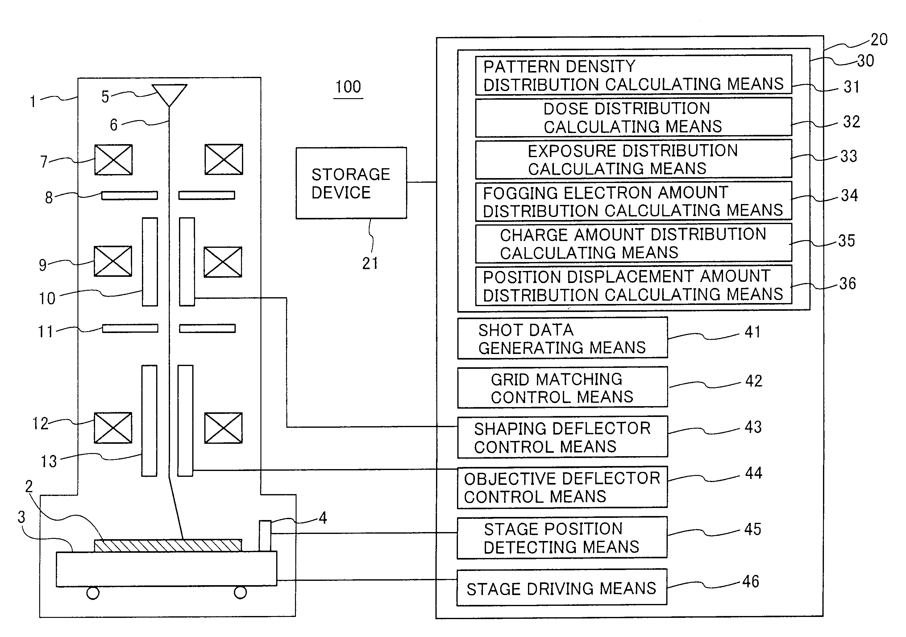
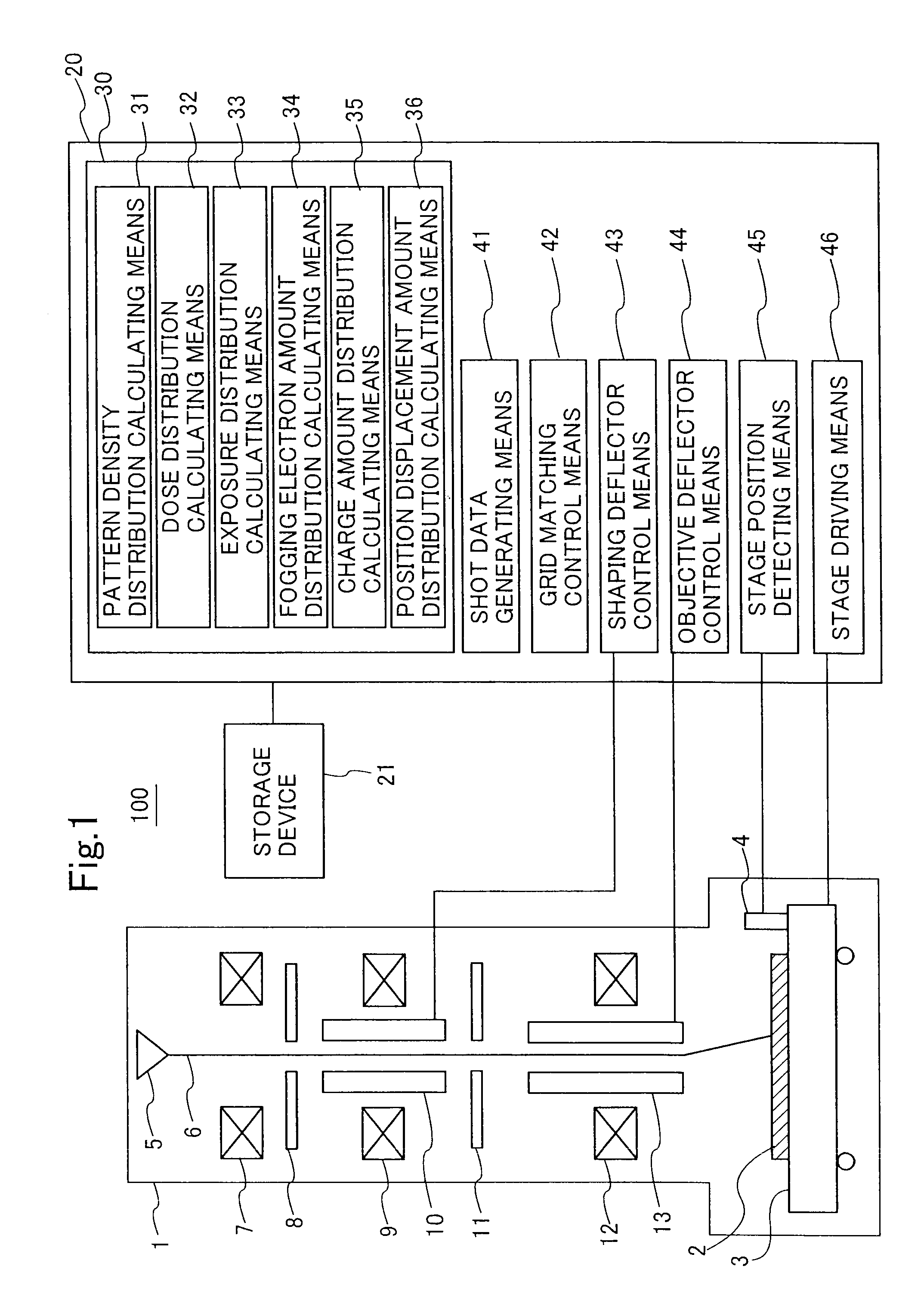
[0076]FIG. 1 is a schematic configuration diagram of an electron beam writing apparatus 100 according to the present embodiment.

[0077]The electron beam writing apparatus 100 of variable-shaped beam system shown in FIG. 1 is equipped with a writing section 1. An XY stage 3 for holding a mask corresponding to a sample 2 is accommodated within the writing section 1. The mask corresponding to the sample 2 is one formed by sequentially laminating a chromium oxide film and a resist layer over a glass substrate. The XY stage 3 is configured so as to be movable in X and Y directions by stage driving means 46 to be described later. The position of movement of the XY stage 3 is detected by stage position detecting means 45 to be described later, based on the output of a laser interferometer 4.

[0078]An electron gun 5 corresponding to a source for the generation of an electron beam 6 is disposed above the XY stage 3. An illuminating lens 7, an S1 aperture (first aperture) 8, a projection lens 9...


PUM


Abstract

A pattern density distribution and a dose distribution calculated using the pattern density distribution are multiplied by each other to calculate an exposure distribution. A fogging electron amount distribution is calculated using the exposure distribution and a function descriptive of a fogging spread distribution. Charge amount distributions in irradiation and non-irradiation regions are calculated using the exposure distribution and the fogging electron amount distribution. A position displacement amount distribution is calculated using the charge amount distributions and a response function for converting a charge amount to a position displacement error.

Description

BACKGROUND OF THE INVENTION[0001]1. Field of the Invention[0002]The present invention relates to a charged-particle beam writing method and a charged-particle beam writing apparatus. More specifically, the present invention relates to the calculation and correction of a position displacement amount of a charged-particle beam due to a charging effect of a sample.[0003]2. Background Art[0004]With the introduction of a double patterning technique, there has been a demand for enhancement of position accuracy of a photomask. With its demand, there has been a demand for an improvement in pattern placement accuracy in the photomask. It has, however, been known that when a pattern of the photomask is written by an electron beam writing apparatus, a beam irradiation position is displaced or shifted due to a resist charging effect.[0005]As one method for correcting this beam irradiation position displacement, there has been known a method for forming a charge dissipation layer (CDL) on a resi...

Claims


Application Information

Patent Timeline
IPC IPC(8): H01J3/14G21K5/10G03F1/76G03F1/78G03F7/20H01L21/027
CPCB82Y10/00B82Y40/00H01J2237/30461H01J37/3174H01J37/3026G03F7/2059G03F7/2063G03F7/70375
Inventor NAKAYAMADA, NORIAKIWAKE, SEIJI
Owner NUFLARE TECH INC
Why Eureka
Try Eureka