Light-emitting device including light-emitting diode

a technology of light-emitting diodes and light-emitting devices, which is applied in the direction of solid-state devices, light and heating apparatuses, spectral modifiers, etc., can solve the problems of reducing conversion efficiency and other problems, and achieve high luminous efficiency, high color rendering properties, and high luminous efficiency.

Inactive Publication Date: 2009-10-01
TOYODA GOSEI CO LTD
View PDF6 Cites 26 Cited by
  • Summary
  • Abstract
  • Description
  • Claims
  • Application Information

AI Technical Summary

Benefits of technology

[0015]The light-emitting device including the LED according to an embodiment of the present invention has the optimized stacking sequence of the plurality of phosphors in view of concentration quenching and thus has high luminous efficiency. In the light-emitting device according to the foregoing embodiment in which the phosphor layers are a red phosphor layer configured to emit red light, a yellow phosphor layer configured to emit yellow light, and a blue phosphor layer configured to emit blue light, since white light is obtained by mixing red, yellow, and blue light, the light-emitting device has high color rendering properties and high luminous efficiency.

Problems solved by technology

A reduction in conversion efficiency is attributed to concentration quenching.

Method used


Image

  • Light-emitting device including light-emitting diode
  • Light-emitting device including light-emitting diode
  • Light-emitting device including light-emitting diode

Examples


first embodiment

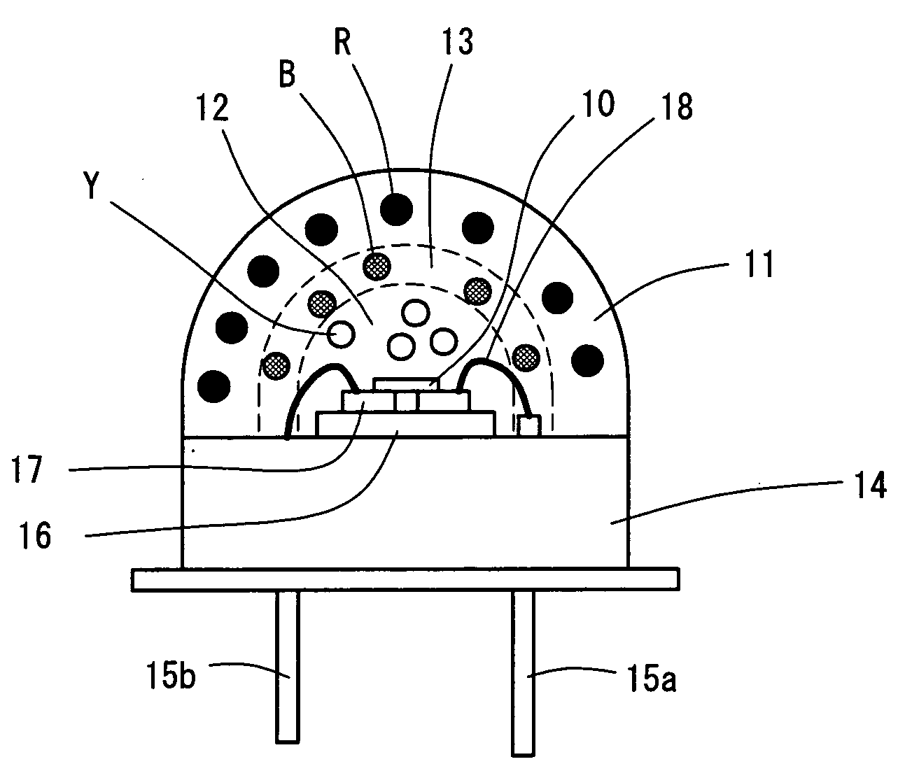
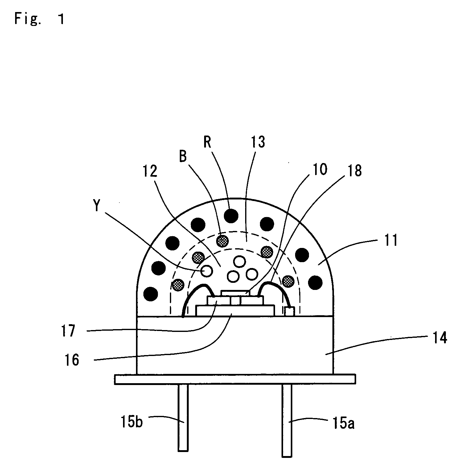
[0019]FIG. 1 illustrates a structure of a light-emitting device including an LED according to a first embodiment. The light-emitting device includes an LED 10 configured to emit ultraviolet light, a red phosphor layer 11, a yellow phosphor layer 12, a blue phosphor layer 13, a metal stem 14, leads 15a and 15b, and a submount 16.

[0020]The LED 10 is a flip-chip element composed of the Group III nitride semiconductor and emits ultraviolet light having a wavelength of 395 nm. The LED 10 is mounted on the submount 16 by flip-chip bonding. Electrodes of the LED 10 are bonded to an electrode pattern 17 arranged on the submount 16 by soldering. The submount 16 is mounted on the metal stem 14. The electrode pattern on the submount 16 is connected to the leads 15a and 15b with wires 18.

[0021]The red phosphor layer 11, the yellow phosphor layer 12, and the blue phosphor layer 13 are stacked on the LED 10. The resulting stack has a dome shape. The yellow phosphor layer 12, the blue phosphor lay...


PUM


Abstract

A light-emitting device includes a light-emitting diode, a red light-emitting phosphor layer, a yellow light-emitting phosphor layer, and a blue light-emitting phosphor layer. These layers are stacked in the stacking sequence of the yellow, blue, and red phosphor layers in order of increasing distance from the LED. The stacking sequence of the yellow and blue phosphor layers is first determined in such a manner that these layers do not interact with each other. The stacking sequence of the red and yellow phosphor layers and the stacking sequence of the red and blue phosphor layers are determined by the discriminant D. This determination of the stacking sequence suppresses a reduction in the conversion efficiency of the phosphors due to concentration quenching, improving the emission efficiency of the light-emitting device.

Description

BACKGROUND OF THE INVENTIONField of the Invention[0001]The present invention relates to a light-emitting device including a light-emitting diode (hereinafter, referred to as an “LED”) and a plurality of stacked phosphor layers, the light-emitting device being configured to emit light having a color different from that of light emitted from the LED.[0002]In recent years, white-light-emitting devices including LEDs have been actively developed for general illumination applications.[0003]It has been reported that a white-light-emitting devices including an LED has an LED configured to emit ultraviolet light and a plurality of phosphors excited by irradiation with ultraviolet light to emit light having colors different from each other, e.g., red, green, and blue, and emits white light by mixing colors of light emitted from the phosphors.[0004]In the case of using different types of phosphors, the interaction among these phosphors is an issue. This is a phenomenon in which light emitted ...

Claims


Application Information

Patent Timeline
Patent Type & Authority Applications(United States)
IPC IPC(8): H01L33/00F21V9/40H01L33/32H01L33/48H01L33/50H01L33/56H01L33/62
CPCH01L33/504H01L2224/48091H01L2924/00014
Inventor INOUE, MITSUHIROITO, KENJITOMITA, KAZUYOHIKACHI, TETSUKOZAWA, TAKAHIROKATO, SATORUICHIKAWA, TADASHI
Owner TOYODA GOSEI CO LTD
Why Eureka
Try Eureka