Ignition device
a technology of ignition device and ignition chamber, which is applied in the direction of sparking plugs, lighting and heating apparatus, instruments, etc., can solve the problems of limiting the improvement of durability and reliability of ignition device, losing energy before growing to a sufficient size needed, and conventional plasma ignition device cannot easily ignite these combustion engines. achieve excellent ignition performan
- Summary
- Abstract
- Description
- Claims
- Application Information
AI Technical Summary
Benefits of technology
Problems solved by technology
Method used
Image
Examples
first embodiment
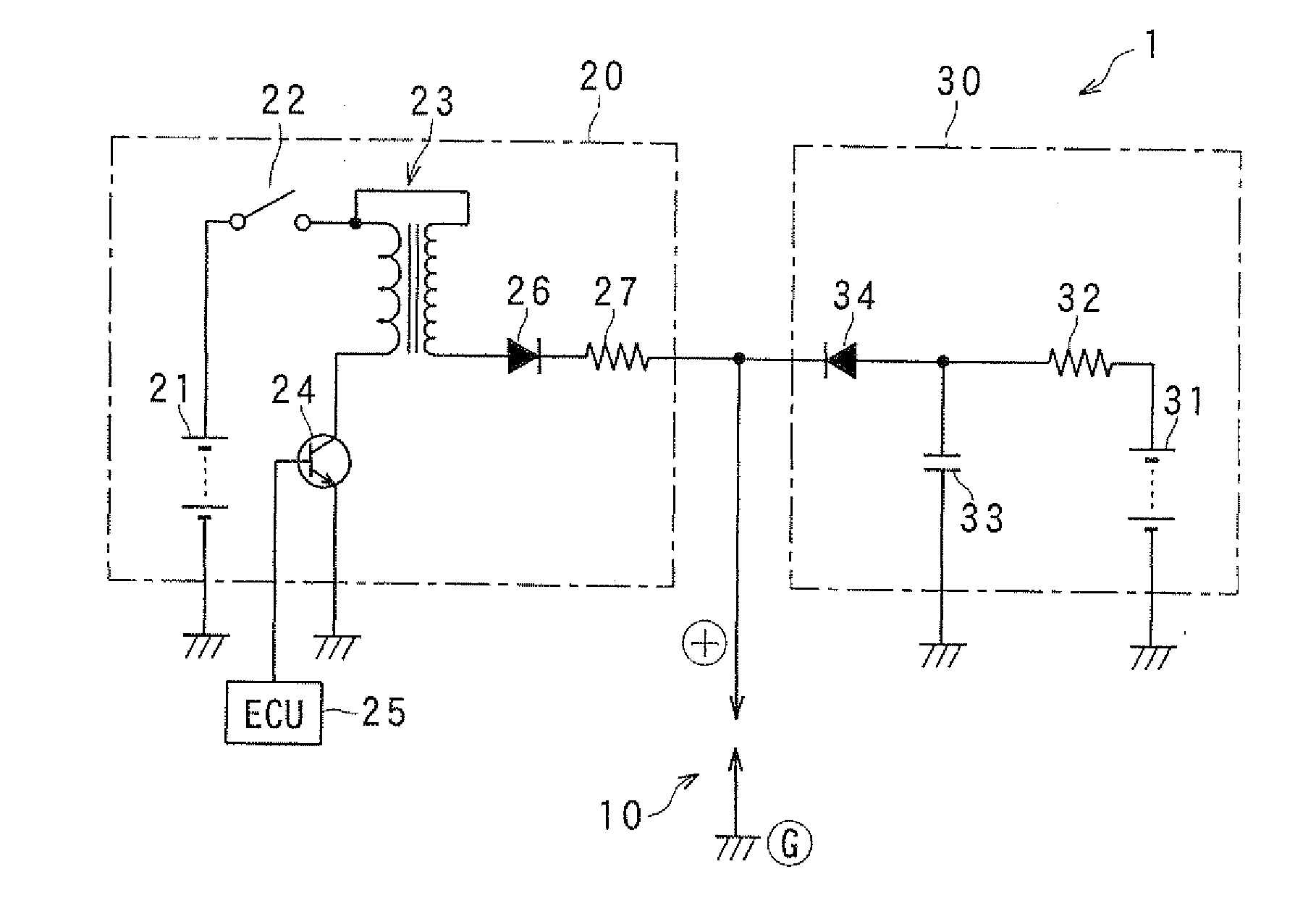
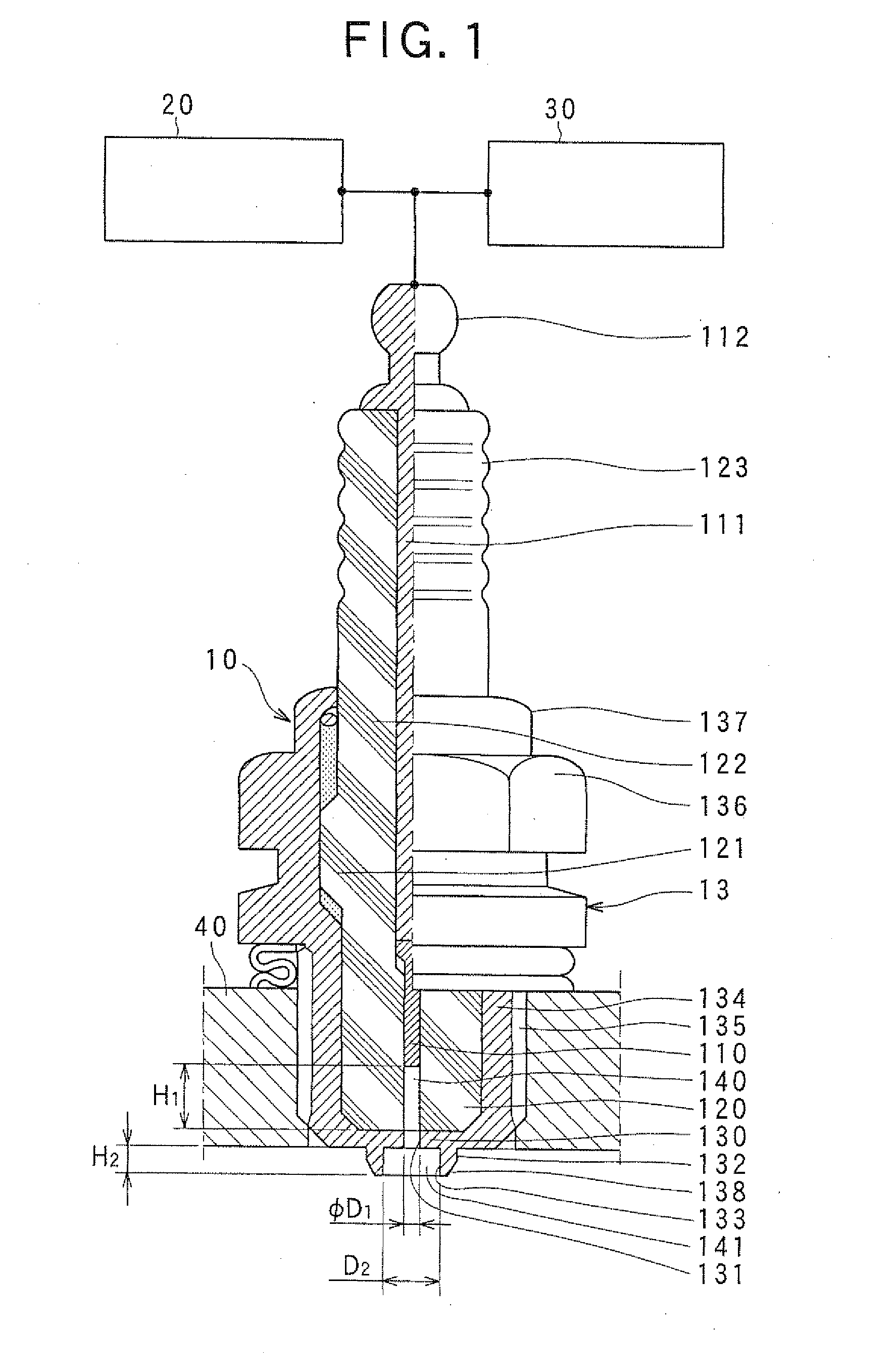
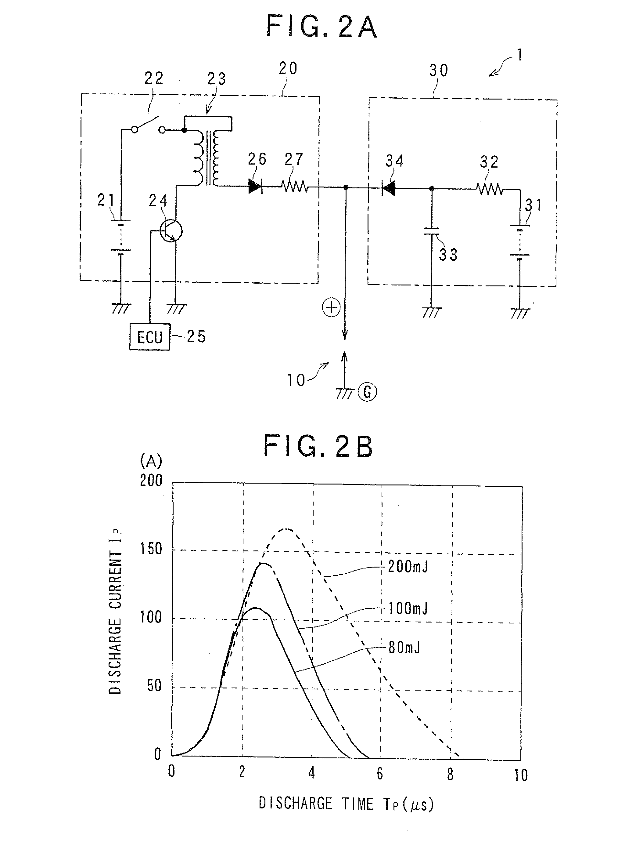
[0082]An ignition device of a first embodiment according to the present invention will be described hereinafter referring to FIG. 1. The ignition device comprises an ignition plug 10, a discharge power source 20 used for supplying high voltage to the ignition plug 10, and a plasma energy supply power source 30 used for supplying high current to the ignition plug 10. The ignition plug 10 is mounted to an engine 40, exposing its apical end in a combustion chamber 400.
[0083]The ignition plug 10 consists of a center electrode 110 having a long shaft shape, an insulator 120 having a tubular shape made for covering and holding the center electrode 110 from its outer circumference in an insulation manner, and a ground electrode 130 having a tubular shape for covering the insulator 120.
[0084]The center electrode 110 is made of material having high heat resistance and good electric conductive performance. The center electrode 110 consists, at its base end side, of a center electrode intermed...
second embodiment
[0163]FIG. 17A is a partial sectional view showing the ignition plug 10c in the present invention. This ignition plug 10c is comprised of a rotational force supply space 141c that is defined by a second open portion 132c prepared by a peripheral wall face 133c.
[0164]The peripheral wall face 133c is formed in the apical end side portion of the first open portion 131c formed in the thickly formed ground electrode 130c. FIG. 17B is a flow analysis view showing a simulation result of the ejected plasma flow 0.35 ms after the plasma ignition plug 10c is provided with high energy. FIG. 17c is an enlarged view of the portion “A” in FIG. 17B.
[0165]FIG. 15A is a partial sectional view showing the ignition plug 10 of the aforementioned first embodiment of the present invention, which has a rotation supply space 141 defined by the tubular peripheral wall face 133 that projects toward the apical end side of the first open portion 131 to surround the first open portion 131.
[0166]FIG. 18B is a f...
third embodiment
[0174]the present invention shown in FIG. 19A comprises a rotation supply space 141d in which the opening diameter of a ground electrode open portion 131d is made larger than the opening diameter of the insulator 120 that forms the discharge space 140.
[0175]This embodiment was found to have the improved ignition performance compared to the conventional plasma ignition device because of the generated vortex rings, like the aforementioned embodiments.
[0176]However, this embodiment was recognized to have the inferior ignition performance compared to the first embodiment, which comprises the tubular second open portions 132, 132a, 132b projecting to the combustion chamber, because of the vortex ring having weaker rotational force.
[0177]This is supposedly caused by unstable growth of the flame kernels. High current applied between the center electrode 110 and the ground electrode 130 generates a creeping discharge that runs on the surface of the insulator 120 inside the discharge space 1...
PUM
 Abstract
Description
Claims
Application Information
 - R&D
- Intellectual Property
- Life Sciences
- Materials
- Tech Scout
- Unparalleled Data Quality
- Higher Quality Content
- 60% Fewer Hallucinations
Browse by: Latest US Patents, China's latest patents, Technical Efficacy Thesaurus, Application Domain, Technology Topic, Popular Technical Reports.
© 2025 PatSnap. All rights reserved.Legal|Privacy policy|Modern Slavery Act Transparency Statement|Sitemap|About US| Contact US: help@patsnap.com


