Quickly replaceable processing-laser modules and subassemblies

a technology of processing lasers and subassemblies, applied in the field of mounted optics, can solve the problems of short operating life and more reliability problems of high-power lasers, needing to be replaced quickly and catastrophically, and affecting the operation of high-power lasers. , to achieve the effect of low cost, high process speed and small physical footprin

Inactive Publication Date: 2009-10-01
NOVASOLAR HLDG
View PDF9 Cites 36 Cited by
  • Summary
  • Abstract
  • Description
  • Claims
  • Application Information

AI Technical Summary

Benefits of technology

[0016]An object of this invention is rapid replacement of processing lasers that use individually calibrated control beams with no need for substantial in situ alignment or recalibration, to reduce down-time resulting from a component failure. Accordingly, the invention includes a lightweight pre-aligned modular assembly that combines a working laser, a control light source, and the beam trains for both light sources on a baseplate with kinematic features that enable the module to be mounted in a self-aligned position on a mating subassembly baseplate.
[0017]Another object of this invention is rapid replacement of groups of processing lasers to reduce down-time, either in the event of performance degradation or to change the process performed by a laser processing tool. Accordingly, the invention includes a kinematically-mounted subassembly of multiple pre-aligned laser modules that can be replaced as a single piece without substantial in situ alignment.
[0022]Other objects of this invention are small physical footprint and high process speed. Accordingly, this invention could include a staggered module-mounting arrangement within a multi-module subassembly so that the working spots can be spaced closer together than the module diameter. This allows simultaneous processing of closely-spaced process targets during a single pass.
[0023]Other objects of this invention are low cost and simplicity. Accordingly, this invention includes a mechanism by which multiple processes can be performed either simultaneously on the same tool, or in series on the same tool with minimal down-time associated with changing lasers.

Problems solved by technology

High-power lasers often have shorter operating lifetimes and more reliability problems than their lower-power counterparts, because high-power lasers routinely exert more thermal, electrical, or other wear and tear on both internal and external components, and they can quickly and catastrophically damage their internal and external optics and mechanics if even a small amount of contaminant that absorbs the laser wavelength—such as a tiny speck of dust or a light film of outgassing residue—enters the beam path on or near a surface.
The more processing lasers a factory operates simultaneously, the greater the probability that a laser or part of its beam train will fail, and need to be replaced, at any given time.
The time it takes to replace the laser on a laser-processing tool is “down-time” that increases ongoing production costs and may lead to costly missed delivery deadlines.
For the reasons discussed above, the working laser and its beam-train optics are often the components most likely to fail.
However, most processing lasers and their optics cannot be quickly replaced when they fail because the unit-to-unit tolerances of these components exceed the alignment sensitivity of the process.
Where multiple components are involved, realignment can take hours, and those hours of downtime add to production overhead costs.
The time, cost, and need frequency of alignments is further increased when laser-processing tools incorporate closed-loop control systems with active mechanisms to make “on-the-fly” adjustments during a processing cycle.
Sometimes the feedback for a closed-loop control system is an attenuated fraction of working laser itself, however, separate control beams are commonly used when the working laser is invisible, pulsed, or operating at a peak power that would damage readily available attenuators and detectors.
However, the lasers in these modules are much lower in power, and both the lasers and the optics are both smaller in size and lighter in weight, than processing lasers and their optics.
Besides, although the prior-art modules often must maintain alignment over a wide range of ambient temperatures, the low-power lasers involved generally create very little heat of their own; nor are thermal effects on the workpiece usually a significant problem either.
For these reasons, kinematic-module solutions that work well for low-power lasers cannot generally be easily adapted to high-power processing lasers.
However, while their beam-positioning tolerance of ±10 μm is acceptable for their application of photocytometry and for some processing applications such as annealing, it is too loose for other applications such as holography and high-precision laser ablation.
Furthermore, while the '488 application's storage of spare lasers in place on the working laser support platform does reduce down-time, many factory environments, such as clean rooms where each cubic foot adds significant expense, cannot cost-effectively spare that much extra space on or around the tool for equipment that is not operating.
Even where the space is available, ambient vibration, local shocks, or thermal cycling could gradually cause the pre-alignment to drift out of tolerance while the replacement lasers are stored on the platform.
While '670 has an advantage of being able to replace either a laser module or an optics module, depending on where the failure occurs, it does not address thermal concerns—possibly because the '670 lasers seem to operate in enclosed cabinets whose temperature may be regulated—or situations where some separate element of a closed-loop control system needs to be calibrated to the individual replacement laser.
From the above discussion, none of the prior-art replaceable modules fully address the needs of high-power working lasers with separate control beams.
Therefore, an unaddressed need exists for such a system.
Therefore, a largely unaddressed need exists for quickly replaceable groups of processing-laser modules that include aligned optics and calibrated control sources for each working laser in the group.

Method used


Image

  • Quickly replaceable processing-laser modules and subassemblies
  • Quickly replaceable processing-laser modules and subassemblies
  • Quickly replaceable processing-laser modules and subassemblies

Examples


Embodiment Construction

[0029]Aspects of this invention improve the cost-effectiveness of replacing processing lasers and optics at three levels: (1) the individual laser-module level, (2) the subassembly level, and (3) the laser platform assembly level.

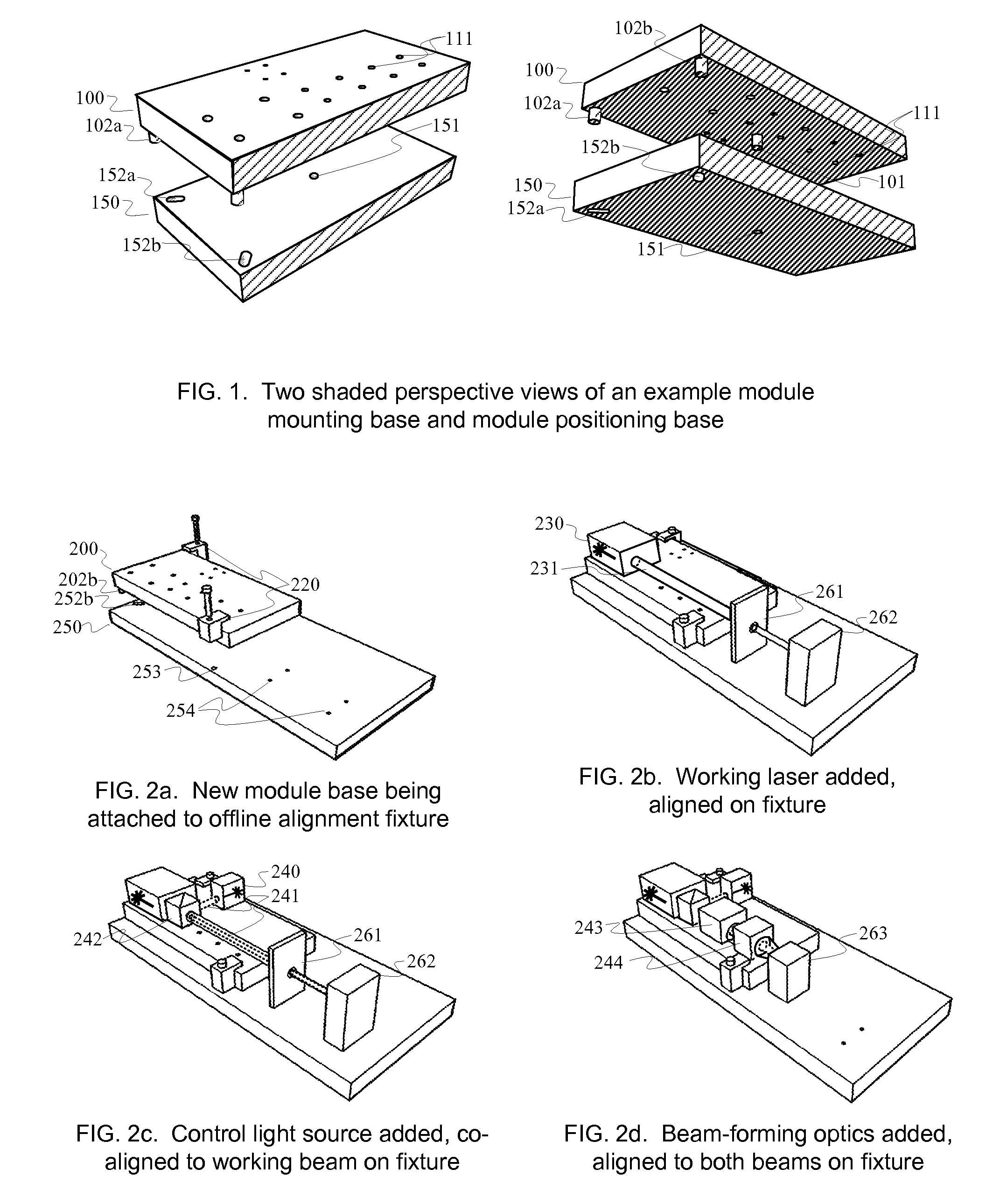
[0030]FIG. 1 shows the basic building block of this invention, a module mounting base (MMB) 100 designed to kinematically mate to a locating surface 150. MMB 100 includes assorted features 111 for attaching the working laser, the control light source, and the mounted optics, mechanics and detectors on the surface shown here as the top. MMB 100 also includes locating features 101, 102a, and 102b on the surface shown here as the bottom. These locating features mate with receiving features 151, 152a, and 152b on locating surface 150. When mated and locked in place by temporary locks (not shown; can be clamps, magnets, bolts, springs, etc.), the locating features and receiving features constrain all the degrees of freedom of motion of MMB 100 with respect to lo...


PUM

PropertyMeasurementUnit
sizeaaaaaaaaaa
temperatureaaaaaaaaaa
thermal expansionaaaaaaaaaa

Abstract

Pre-aligned, kinematically mounted modules including processing lasers, beam trains, and individually calibrated control beams are quickly and easily replaced on subassembly bases with minimal in situ alignment, and can maintain working-spot position to micron tolerances over ambient temperature variations of ±10° C. Subassembly bases, with features for kinematically mating to a plurality of pre-aligned laser modules and to a platform base incorporated in the laser processing tool, enable multi-module subassemblies to be quickly replaced with spare subassemblies of the same type, or swapped for subassemblies of a different type. The mating features and reversible locks are designed to mitigate thermal effects that are often a dominant cause of alignment drift in processing lasers.

Description

RELATED APPLICATIONS[0001]NoneFEDERALLY SPONSORED RESEARCH AND DEVELOPMENT[0002]NoneAPPENDICES[0003]NoneBACKGROUND OF THE INVENTION[0004]This invention is related to mounted optics for laser processing of materials, particularly where the lasers are controlled by a closed-loop system using feedback data from a “control” beam that measures or illuminates, but does not process, the material. This invention is particularly applicable to ablation laser systems controlled by autofocus mechanisms, but can also be useful in laser cutting, welding, or annealing systems that use control beams to track and correct beam-pointing errors or to illuminate markers or fiducials.[0005]Laser processing tools are widely used in many industries. Factories mass-producing high-precision components or products often have tens or hundreds of working lasers operating simultaneously. Processing lasers generally produce much more powerful beams than most lasers used in other common applications such as displa...

Claims


Application Information

Patent Timeline
Patent Type & Authority Applications(United States)
IPC IPC(8): B23K26/00H01S3/08
CPCB23K26/046B23K26/0604B23K26/20B23K26/367Y10T29/49826H01S3/025H01S3/2383Y10T29/49904Y10T29/49895B23K26/38B23K26/364B23K26/21
Inventor CLIFFORD, JR., GEORGE M.
Owner NOVASOLAR HLDG
Why Eureka
Try Eureka