Receiver on a photonic IC

a photonic ic and receiver technology, applied in the field of optical communication devices, can solve the problems of large footprint, increased manufacturing costs, and large amount of optical and electrical circuitry for demodulation of dqpsk signals or other signals transmitted in accordance with a self-coherent scheme, and achieve the effect of high capacity

Active Publication Date: 2009-10-01
INFINERA CORP
View PDF9 Cites 23 Cited by
  • Summary
  • Abstract
  • Description
  • Claims
  • Application Information

AI Technical Summary

Benefits of technology

[0007]Exemplary embodiments of the present invention are directed to a high capacity optical receiver. In an exemplary embodiment, an optical receiver includes a first substrate including a demultiplexer and a first optical waveguide array. An input of the demultiplexer is configured to receive a wavelength division multiplexed optical input signal having a plurality of channels. Each of the plurality of channels corresponds to one of a plurality of wavelengths. Each of the plurality of outputs is configured to supply a correspond

Problems solved by technology

On the receive side of such a communication system, the demodulation of DQPSK signals or other signals transmitted in accordance with a self-coherent scheme require a considerable amount of optical and electrical circuitry.
However, implementing an optical receiver requires tight tolerances to properl

Method used


Image

  • Receiver on a photonic IC
  • Receiver on a photonic IC
  • Receiver on a photonic IC

Examples


Embodiment Construction

[0018]The present invention will now be described more fully hereinafter with reference to the accompanying drawings, in which preferred embodiments of the invention are shown. This invention, however, may be embodied in many different forms and should not be construed as limited to the embodiments set forth herein. Rather, these embodiments are provided so that this disclosure will be thorough and complete, and will fully convey the scope of the invention to those skilled in the art. It will be understood that when an element or component is referred to herein as being “connected” or “coupled” to another element, it can be directly connected or coupled to the other element or intervening elements may be present therebetween. In contrast, when an element is referred to as being “directly connected” or “directly coupled” to another element, there are no intervening elements present. In the drawings, like numbers refer to like elements throughout.

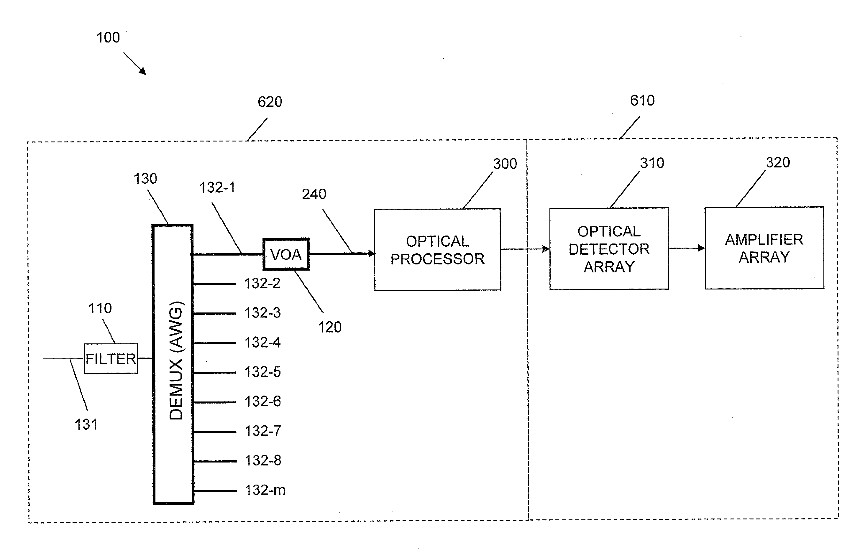
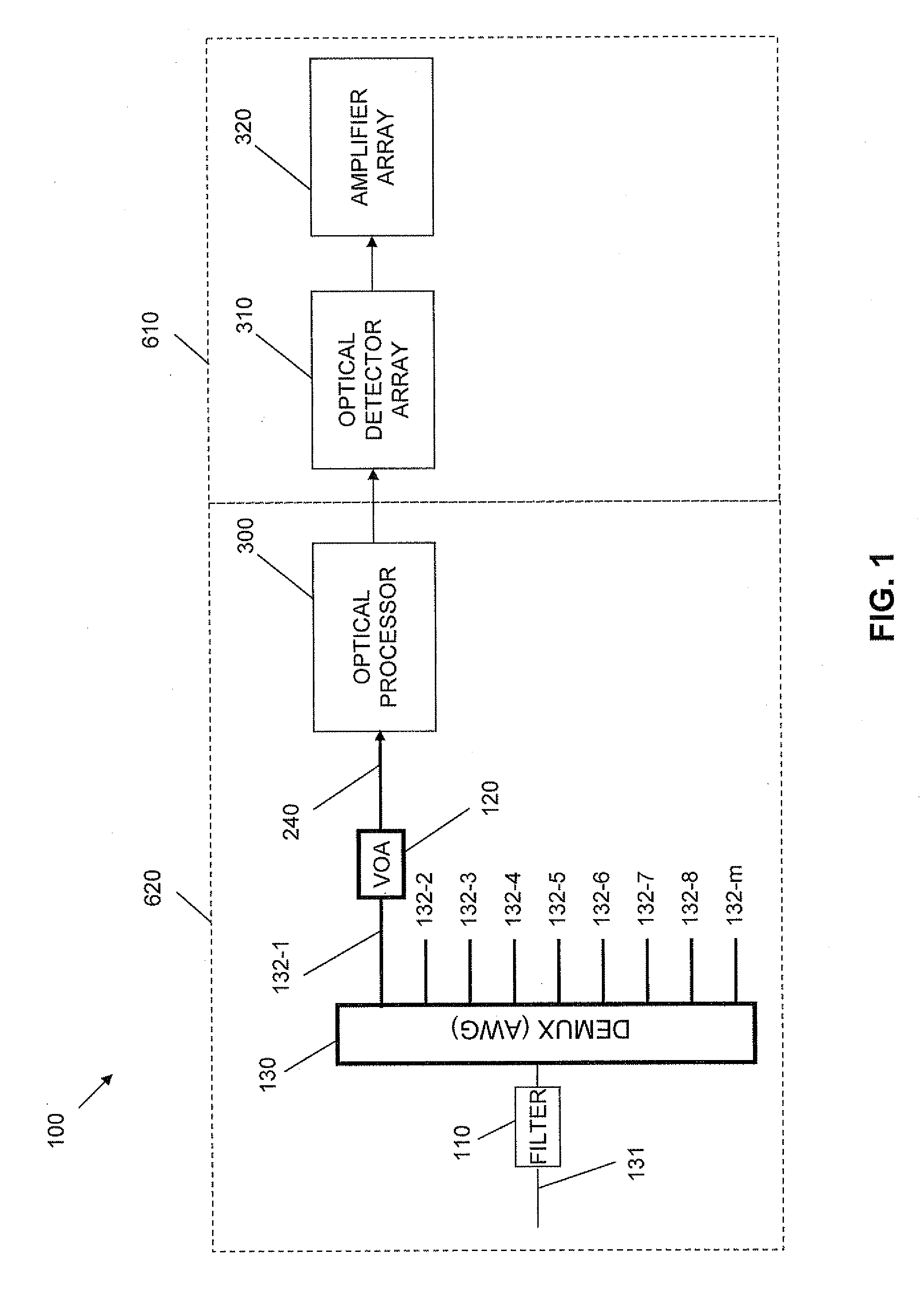
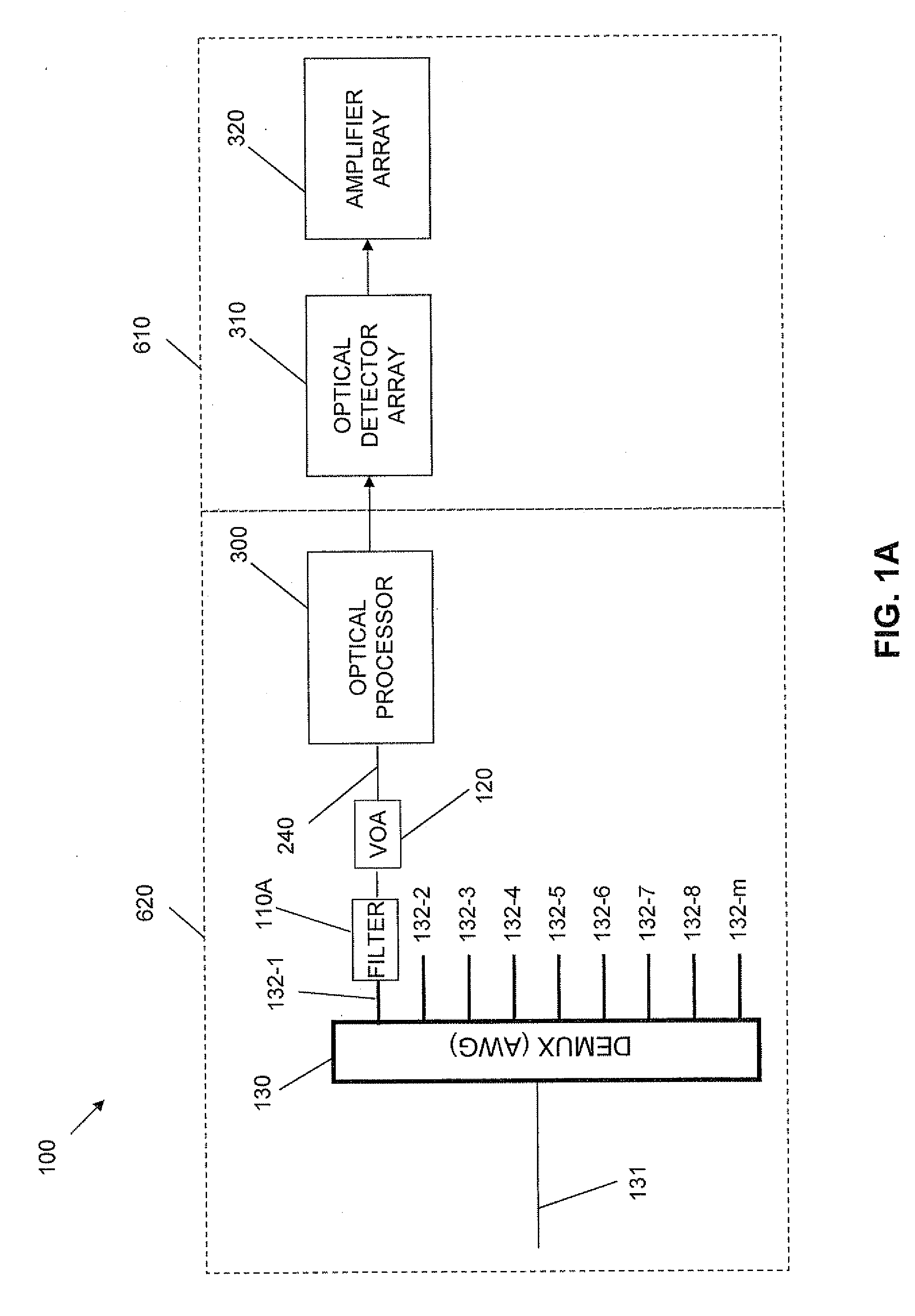
[0019]FIG. 1 illustrates a block diagr...


PUM


Abstract

An optical receiver includes a first substrate including a demultiplexer and a first optical waveguide array. An input of the demultiplexer is configured to receive a wavelength division multiplexed optical input signal having a plurality of channels. Each of the plurality of channels corresponds to one of a plurality of wavelengths. Each of the plurality of outputs is configured to supply a corresponding one of the plurality of channels. The first optical waveguide array has a plurality of inputs. Each of the inputs of the first optical waveguide array is configured to receive a corresponding one of the plurality of channels. A second substrate is in signal communication with the first substrate and includes an optical detector array. The optical detector array has a plurality of inputs, each of which is configured to receive a corresponding one of the plurality of channels and generate an electrical signal in response thereto.

Description

CROSS-REFERENCE TO RELATED APPLICATIONS[0001]This application claims priority to U.S. Provisional Application No. 61 / 030,782 filed Feb. 22, 2008 which is herein incorporated by reference in its entirety.BACKGROUND[0002]1. Field of the Invention[0003]Embodiments of the invention relate to the field of optical communication devices. More particularly, the present invention relates to a receiver used for optical communication systems implemented on a planar lightwave circuit and a photonic integrated circuit.[0004]2. Discussion of Related Art[0005]Wavelength division multiplexed (WDM) optical communication systems are known in which multiple optical signals, each having a different wavelength, are combined onto a single optical fiber. Such systems typically include a laser associated with each wavelength, a modulator configured to modulate the output of the laser, and an optical combiner to combine each of the modulated outputs. Conventionally, WDM systems have been constructed from di...

Claims


Application Information

Patent Timeline
IPC IPC(8): H04J14/02
CPCG02B6/12004G02B6/12007H04J14/06H04J14/02H04J14/0221H04B10/677
Inventor LITTLE, BRENT E.CHEN, WEIHRYNIEWICZ, JOHN V.CHU, SAI T.RAHN, JEFFZIARI, MEHRDADBUTRIE, TIMOTHYREFFLE, MICHAELKISH, JR., FRED A.JOYNER, CHARLES H.
Owner INFINERA CORP
Why Eureka
Try Eureka