Wind turbine protection

a wind turbine and protection technology, applied in the field of wind turbine protection, can solve the problems of multiple punctures (or stitching) of the blade surface, high incidence of thunder storms, and damage to the blade often, and achieve the effect of improving supply reliability

Inactive Publication Date: 2009-10-01
GENERAL ELECTRIC CO
View PDF8 Cites 35 Cited by
  • Summary
  • Abstract
  • Description
  • Claims
  • Application Information

AI Technical Summary

Benefits of technology

[0019]According to a fifth aspect of the present invention, a method of generating electricity is provided. The method comprises operating a wind turbine according to the fourth aspect of the present invention and supplying the electricity generated to an electricity grid for subsequent consumption by a consumer. One advantage of such a method is that supply reliability is improved, particularly in stormy weather and thundercloud conditions.

Problems solved by technology

However, such regions tend to be located in the more inhospitable and remote parts of the world, and further often suffer from a relatively high incidence of thunder storms.
However, such high speed rotation, in combination with the unpredictability of the lightning discharge direction, can cause a lightning strike in which the strike discharge on a turbine blade does not remain at a static position, but which instead attaches to and moves over the turbine blade's surface.
This in turn can lead to so-called swept strokes that may result in multiple punctures (or stitching) of the blade's surface.
Moreover, even where such multiple punctures do not occur, the final breakdown of the lightning is likely to appear at the trailing edge of the struck blade, and this is one reason why most turbine blade damage often occurs at this edge.
Hence, whilst conventional lightning protection systems are usually better than no protection at all, it is not uncommon for the blades of wind turbines using such conventional lightning protection systems to suffer from delamination of their trailing edges and / or from damage caused by swept strokes when they are struck by lightning.

Method used


Image

  • Wind turbine protection
  • Wind turbine protection
  • Wind turbine protection

Examples


Embodiment Construction

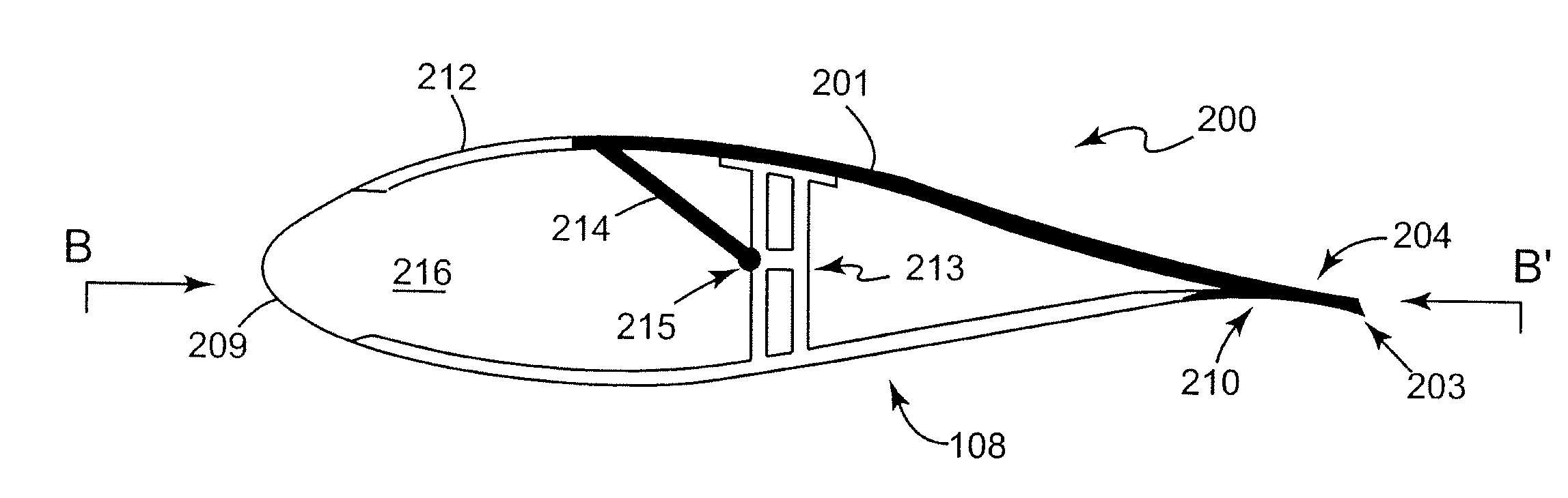
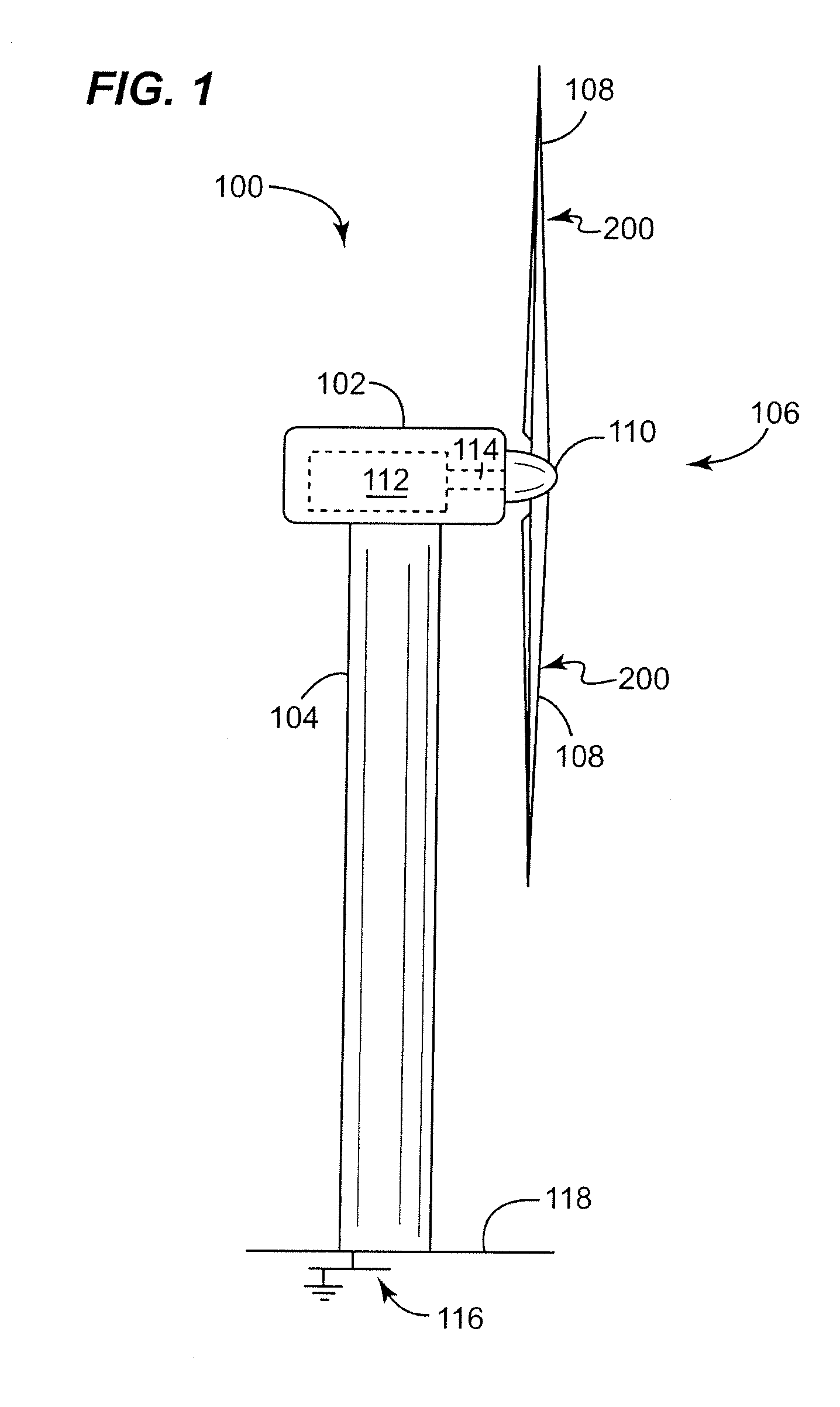
[0032]FIG. 1 shows an embodiment of a wind turbine 100 according to the present invention. The wind turbine 100 includes a nacelle 102, a tower 104, and a rotor 106 having at least one rotor blade 108 and a rotateable hub 110. The nacelle 102 is mounted on the tower 104 and also houses an electrical generator 112. Rotor blades 108 are attached to the hub 110 and rotate the hub 110 when there is sufficient wind strength to move the blades 108. The hub 110 is mechanically coupled to the generator 112 by a coupling mechanism 114, which may comprise a gear mechanism (not shown), such that rotation of the hub 110 causes operation of the electrical generator 112 to generate electricity.

[0033]The structure of the tower 104 comprises a lightning conductor or down-conductor (not shown for clarity) for electrically coupling to a ground potential at a first end thereof. The first end of the lightning conductor is connected to an earth potential via an earth / ground plate 116 embedded in soil 11...


PUM


Abstract

A lightning protection system for a wind turbine blade of a wind turbine includes a conductive lightning receptor for mounting at the surface of a turbine blade such that a portion of the lightning receptor projects beyond a trailing edge of the turbine blade when mounted at the surface. Another lightning protection system includes a lightning receptor that has a generally elongated shape and that is configured to be mounted such that the greatest dimension of the lightning receptor lies generally parallel to the direction in which the turbine blade is designed to move.

Description

CROSS REFERENCE TO RELATED APPLICATION[0001]This application claims priority to EP Application Serial No. 07113032.2 filed Jul. 24, 2007, incorporated in its entirety herein by reference.BACKGROUND[0002]The systems disclosed herein relate generally to the protection of wind turbines, such as those used for generating electricity for example. More particularly, the systems disclosed herein relate to lightning protection for wind turbines.[0003]Recently the use of renewable energy sources to generate electricity has grown enormously as environmental issues have become prominent in the public's mind. One such energy source that has found great favour is the wind turbine.[0004]In order to operate efficiently, and extract the maximum useful energy from wind, wind turbines are necessarily situated in relatively windy regions whenever possible. However, such regions tend to be located in the more inhospitable and remote parts of the world, and further often suffer from a relatively high in...

Claims


Application Information

Patent Timeline
Patent Type & Authority Applications(United States)
IPC IPC(8): F03D11/00
CPCF03D1/0675Y02E10/722Y02E10/721F03D11/0033F05B2230/80F03D80/30Y02E10/72Y02P70/50
Inventor LEWKE, BASTIANKRAEMER, SABASTIANMENDEZ HERNANDEZ, YARU
Owner GENERAL ELECTRIC CO
Why Eureka
Try Eureka