Catalyst-carrying filter

a filter and catalyst technology, applied in the direction of raney catalysts, metal/metal-oxides/metal-hydroxide catalysts, metal catalysts, etc., can solve the problems of ineffective utilization of oxidizing catalysts, inability to reduce the amount of particulate matter contained in exhaust gas, and environmental pollution, so as to improve catalyst purification performance, improve regeneration efficiency, and reduce pressure loss

Inactive Publication Date: 2009-10-01
NGK INSULATORS LTD
View PDF5 Cites 20 Cited by
  • Summary
  • Abstract
  • Description
  • Claims
  • Application Information

AI Technical Summary

Benefits of technology

[0032]The catalyst-carrying filter according to the present invention exhibits an improved catalyst purification performance, an improved regeneration efficiency, a reduced pressure loss due to soot, and an improved emission by forming the PM removal catalyst layer that supports or is coated with the oxidizing catalyst for promoting oxidation of particulate matter contained in exhaust gas in the gas-inflow-side layer (soot deposition layer) of the partition wall and forming the PM collection layer that has a small average pore size so as to collect particulate matter, and the gas purification catalyst layer that supports the gas purification catalyst that promotes oxidation of unburnt gas in the gas-outflow-side layer of the partition wall. The catalyst-carrying filter can efficiently remove PM and unburnt gas even when installed und...

Problems solved by technology

When particulate matter is directly discharged to the atmosphere, environmental pollution occurs.
However, when using a catalyst-carrying filter formed of a porous ceramic having an average pore size that ensures that particulate matter contained in exhaust gas can be reliably collected, most of particulate matter contained in exhaust gas is deposited on the surface of the partition wall that faces the exhaust-gas-inflow cell, and does not reach the inside of the pores formed in the partition wall.
Specifically, since the oxidizing catalyst supported on the inner surface of the pore formed in the partition wall does not come in contact with particulate matter, the oxidizing catalyst is not effectively utilized.
Therefore, since oxidation (combustion) of particulate matter cannot be promoted sufficiently, the amount of particulate matter contained in exhaust gas cannot be reduced.
In particular, when a DPF formed of such a catalyst-carrying filter is installed under the vehicle floor, since soot discharged from the engine aggregates (i.e., increases in diameter) before reaching the DPF, soot is deposited in the gas-inflow-side layer so that a pressure loss is likely to occur.
Therefore, it is substantiall...

Method used


Image

  • Catalyst-carrying filter
  • Catalyst-carrying filter
  • Catalyst-carrying filter

Examples


examples

[0129]The present invention is further described below by way of examples. Note that the present invention is not limited to the following examples. In the examples and comparative examples, “part” and “%” respectively refer to “part by mass” and “mass %” unless otherwise indicated. In the examples and comparative examples, properties were evaluated and measured by the following methods.

1 DPF

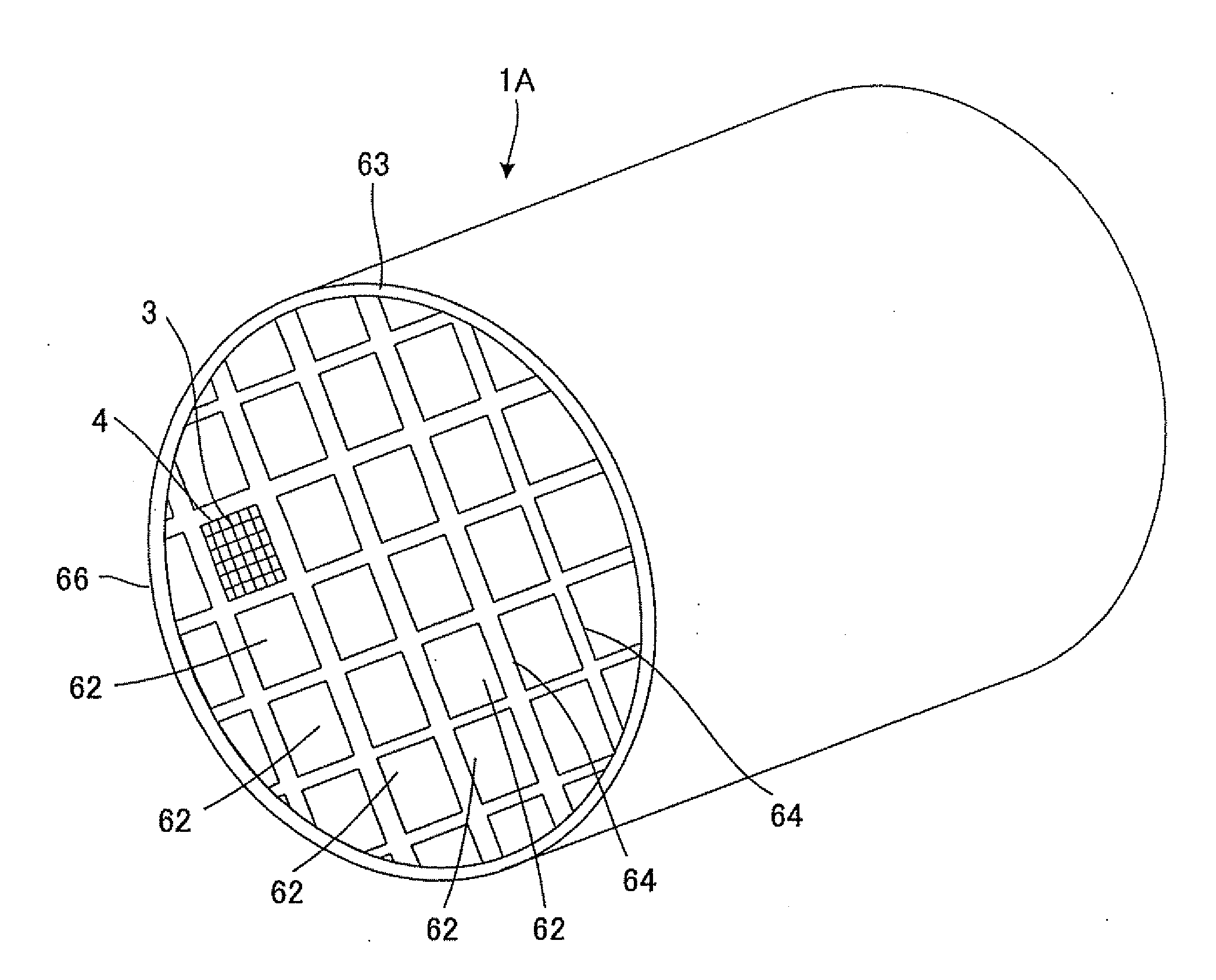
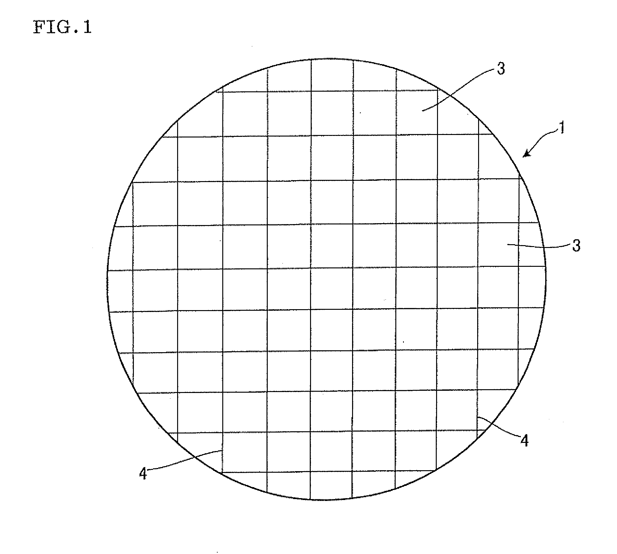
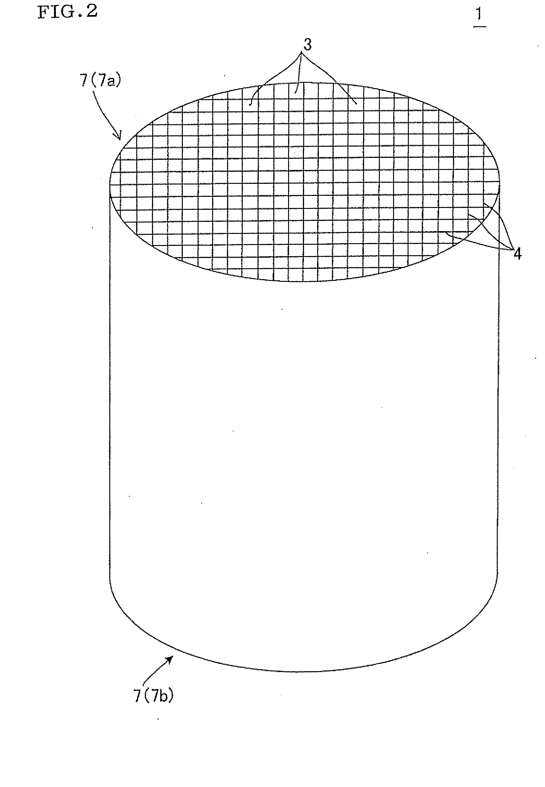
[0130]In the examples and comparative examples, a catalyst-carrying filter was produced using a honeycomb structure described below.

[0131]A honeycomb structure (i.e., base material of catalyst-carrying filter) was produced as follows. A mixed powder of 80 mass % of an SiC powder and 20 mass % of an Si metal powder was used as the raw material. Methyl cellulose, hydroxypropoxylmethyl cellulose, a surfactant, and water were added to the mixed powder to prepare a plastic clay. The clay was extruded using an extruder to obtain sixteen (4×4) honeycomb segments having the desired dimensions. The honey...

examples 1 to 6

[0135]Catalyst-carrying filters of Examples 1 to 6 were obtained from the SiC-DPF described above in the same manner as described above, except for setting the porosity of the gas-inflow-side layer at 60%, setting the pore size of the gas-inflow-side layer at 50 μm, setting the porosity of the gas-outflow-side layer at 40%, setting the pore size of the gas-outflow-side layer at 5 μm, causing the catalyst A to be supported (applied) as the PM removal catalyst, and causing the catalyst A to be supported (applied) as the gas purification catalyst. The catalyst amount ratio, the total catalyst amount, and the like are shown in Table 1.

examples 7 and 8

[0136]Catalyst-carrying filters of Examples 7 and 8 were obtained form the SiC-DPF described above in the same manner as described above, except for setting the porosity of the gas-inflow-side layer at 60%, setting the pore size of the gas-inflow-side layer at 50 μm, setting the porosity of the gas-outflow-side layer at 40%, and setting the pore size of the gas-outflow-side layer at 1 μm, or setting the porosity of the gas-inflow-side layer at 60%, setting the pore size of the gas-inflow-side layer at 50 μm, setting the porosity of the gas-outflow-side layer at 40%, and setting the pore size of the gas-outflow-side layer at 15 μm, causing the catalyst A to be supported (applied) as the PM removal catalyst, and causing the catalyst A to be supported (applied) as the gas purification catalyst. The catalyst amount ratio, the total catalyst amount, and the like are shown in Table 1.


PUM

PropertyMeasurementUnit
Pore sizeaaaaaaaaaa
Pore sizeaaaaaaaaaa
Densityaaaaaaaaaa

Abstract

A catalyst-carrying filter has a partition wall that includes a gas-inflow-side layer and a gas-outflow-side layer. One open end and the other open end of a plurality of cells are alternately plugged by plugging sections. The gas-inflow-side layer of the partition wall includes a PM removal catalyst layer that supports or is coated with an oxidizing catalyst for promoting oxidation of particulate matter contained in exhaust gas. The gas-outflow-side layer of the partition wall includes a PM collection layer that has a small average pore size so as to collect particulate matter, and a gas purification catalyst layer that supports or is coated with a gas purification catalyst that promotes oxidation of unburnt gas.

Description

BACKGROUND[0001]1. Field of the Invention[0002]The present invention relates to a catalyst-carrying filter that is used to collect or purify particulate matter contained in exhaust gas discharged from an internal combustion engine (e.g., diesel engine) or a combustion apparatus.[0003]2. Description of Related Art[0004]Exhaust gas discharged from an internal combustion engine (e.g., diesel engine) or a combustion apparatus (hereinafter may be collectively referred to as “internal combustion engine or the like”) contains a large amount of particulate matter (hereinafter may be referred to as “PM”) that mainly contains soot (graphite). When particulate matter is directly discharged to the atmosphere, environmental pollution occurs. Therefore, a filter that collects particulate matter is generally provided in an exhaust gas passage connected to an internal combustion engine or the like.[0005]For example, a honeycomb filter shown in FIG. 8 is used for such a purpose. The honeycomb filter...

Claims


Application Information

Patent Timeline
IPC IPC(8): B01J23/00
CPCB01D53/944B01D2255/1021B01D2255/407B01D2255/9022F01N2510/065B01D2255/9205F01N3/0222F01N3/0231F01N3/035B01D2255/908
Inventor MIZUTANI, TAKASHI
Owner NGK INSULATORS LTD
Why Eureka
Try Eureka