Percutaneous aortic valve assembly

a technology of aortic valve and aortic valve, which is applied in the field of percutaneous aortic valve assembly, can solve the problems of limited success, inability to surgically manage patients, and inability to achieve the effect of percutaneous treatment of valvular heart disease, and achieve safe and accurate placement of valves. , the effect of increasing blood flow

Inactive Publication Date: 2009-10-01
BETH ISRAEL DEACONESS MEDICAL CENT INC
View PDF10 Cites 80 Cited by
  • Summary
  • Abstract
  • Description
  • Claims
  • Application Information

AI Technical Summary

Benefits of technology

[0006]In one aspect, the invention provides devices and methods for the treatment of aortic valve disease. A percutaneous aortic valve according to the invention directs the flow of blood out of the left ventricle, functionally elongates the left ventricular outflow tract (in particular the aortic annulus), limits the flow of blood back into the ventricle, and augments the blood flow through the coronary arteries. This approach yields the advantages of both a surgical and catheter-based approach, namely, safe and accurate placement of a valve between the left ventricle and the aorta as in surgery with reliable access to the aortic-ventricular junction using a catheter-based approach without the need for a surgical incision.

Problems solved by technology

However, many patients are not candidates for surgical management due to advanced age or co-morbidities such as severe lung disease or renal failure.
Percutaneous treatment of valvular heart disease has only been successful in congenital stenosis, rheumatic mitral stenosis (amenable to valvuloplasty), and as a palliative or bridge procedure in adult aortic stenosis with limited success.
For example, balloon aortic valvuloplasty may achieve some relief of symptoms in calcific aortic stenosis with high vascular complication rates and universal relapse and no survival benefit.
However, the devices available are very large, thus increasing access site complication (necessitating surgery), increasing risk of damage to cardiac structures, and limiting length of the anchoring device (stent), since it has to be flexible.
The current percutaneous valve designs require 21 or 24 French sheaths for delivery, resulting in the inability to deliver in patients with concomitant pulmonary vascular disease and also in a high rate of vascular complications.
Some valves are available in only one size, which results in paravalvular leaks in many patients as well as in more serious conditions such as device embolization and migration.

Method used


Image

  • Percutaneous aortic valve assembly
  • Percutaneous aortic valve assembly
  • Percutaneous aortic valve assembly

Examples


Embodiment Construction

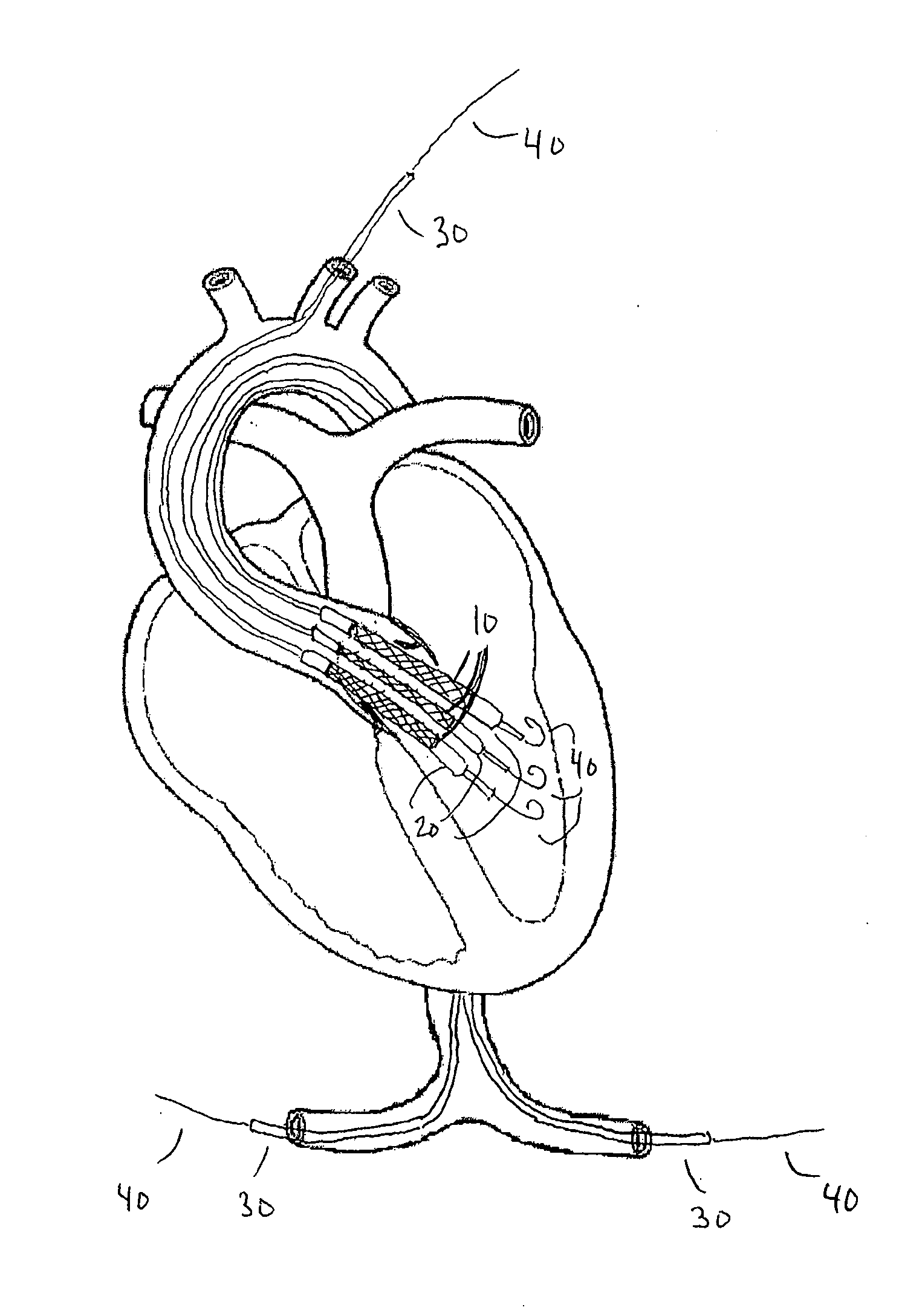
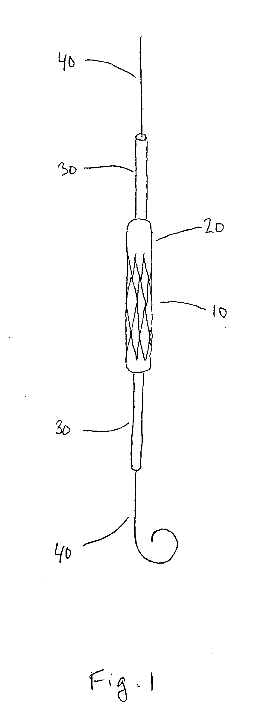
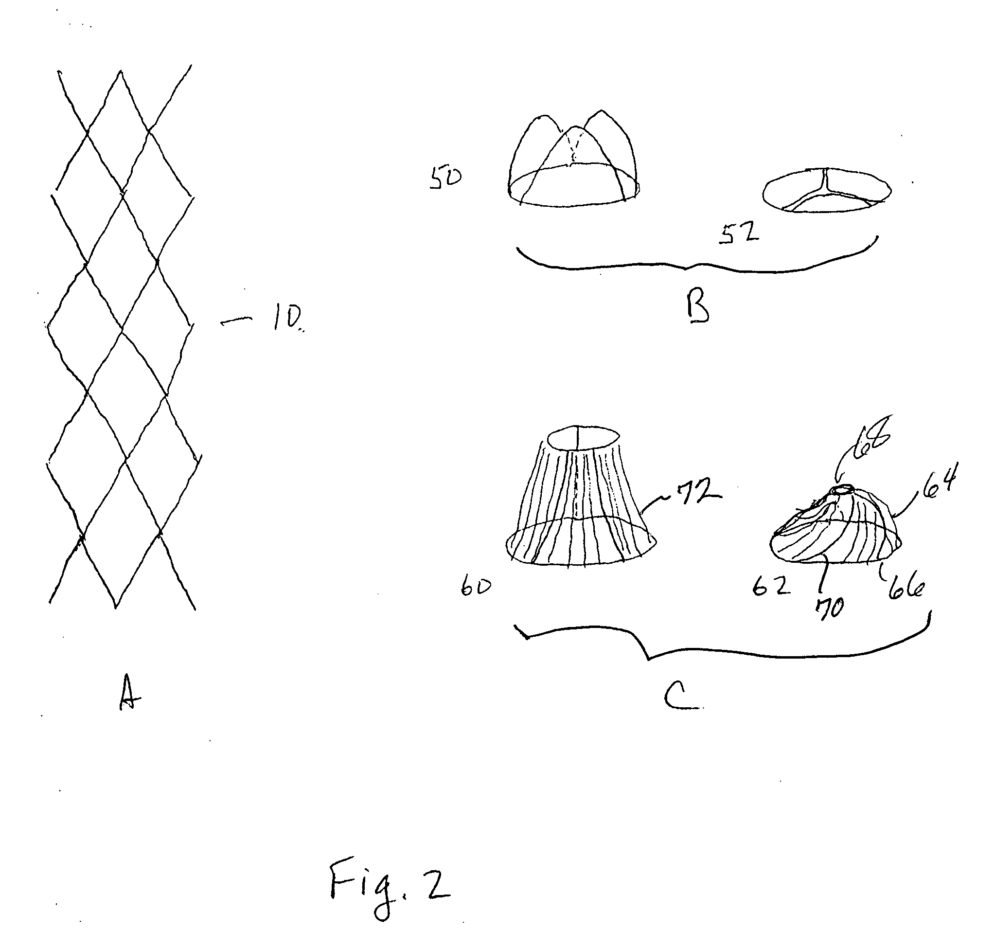
[0015]The present invention relates to valving methods and devices that address many of the issues surrounding percutaneous valve replacement, including access site complications, flexibility, length of anchoring components, risk of stroke, and damage to cardiac structures. A preferred embodiment includes implanting several smaller valve devices that are assembled at the site of valve replacement to form a larger valve assembly. Each valve device contains a valve mounted within a stent. The valve assembly is a compound valve, containing two or more valve devices, each with its own valve structure. The stents are sufficiently long, flexible, and textured so that, when expanded, they apply a lateral force against the vessel wall and against each other which is sufficient to prevent significant backflow around or through the valve assembly and sufficient to prevent migration of the valve assembly. Since the valve assembly is built up at the site of valve replacement, the individual val...


PUM


Abstract

The present invention provides devices and methods for the treatment of cardiovascular valve diseases such as aortic stenosis. A vascular valve assembly is formed from two or more valve devices, each of which contains a valve mounted in a stent. The individual valve devices are brought to the site of the defective valve by standard percutaneous catheterization methods. Lateral expansion of the stents at the site of valve replacement produces a functioning valve assembly. Appropriate sizing and number of valve devices prevents regurgitation and migration. The assembly of two or more smaller valve devices at the site of a defective valve prevents complications due to the large size of single valve prostheses.

Description

CROSS REFERENCE TO RELATED APPLICATION[0001]This application claims the priority of U.S. Provisional Application No. 60 / 853,995 filed on Oct. 24, 2006, the entire contents of which is incorporated herein by reference.BACKGROUND OF THE INVENTION[0002]Heart valve disease can progress to the point that a valve must be repaired or replaced in order to improve the quality and / or length of life of the afflicted patient. Surgical aortic valve replacement is the only accepted treatment for calcific degenerative aortic stenosis as well as for aortic regurgitation, mitral regurgitation, and right sided valvular disease. Surgery for heart valve disease allows for the accurate replacement and repair of diseased heart valves. Traditionally, patients have had to undergo open heart surgery to treat heart valve disease. However, many patients are not candidates for surgical management due to advanced age or co-morbidities such as severe lung disease or renal failure.[0003]There have been efforts to...

Claims


Application Information

Patent Timeline
Patent Type & Authority Applications(United States)
IPC IPC(8): A61F2/82
CPCA61F2/2418A61F2/2433A61F2/2475A61F2230/0008A61F2250/0062A61F2220/0016A61F2220/005A61F2/848
Inventor LAHAM, ROGER J.
Owner BETH ISRAEL DEACONESS MEDICAL CENT INC
Why Eureka
Try Eureka