Solar-To-Electricity Conversion Sub-Module

a technology of solar energy and conversion sub-module, which is applied in the direction of thermal-pv hybrid energy generation, pv power plants, sustainable buildings, etc., can solve the problems of reducing affecting the efficiency of solar energy conversion, and affecting the conversion efficiency of solar energy

Inactive Publication Date: 2009-10-08
PAN ERIC TING SHAN
View PDF68 Cites 7 Cited by
  • Summary
  • Abstract
  • Description
  • Claims
  • Application Information

AI Technical Summary

Benefits of technology

[0042]A further aspect concerns a solar-to-electricity conversion system configured in a modular platform and comprising: a photon-to-electricity subsystem including a linear cascade arrangement of two or more successive spaced photovoltaic cells, each of the cells having a different band gap to convert concentrated insolation flux within a flux path into electrical energy; a heat-to-electricity conversion subsystem also situated immediately before or after the photon-to-electricity subsystem within the linear cascade arrangement and flux path and including at least one of an array of thermoelectric cells or thermionic cells to convert heat into electric energy; a heat sink/pipe coupled to the photon-to-electricity subsystem and/or the heat-to-electricity conversion subsystem; a plurality of thermal expansion matched multilayer boards, one for each of the photovoltaic cells and the array of thermoelectric or thermionic cells; and a casing assembly for mounting the photon-to-electricity subsystem, the heat-to-electricity conversion subsystem, the heat sink/pipe, the plurality of thermal expansion matched multilayer boards and the light cavity.
[0043]In preferred embodiments the two or more successive spaced photovoltaic cells include the following: a first photovoltaic cell of band gap at about 2.54 eV; a second photovoltaic cell of band gap at about 1.47 eV; and a third photovoltaic cell of band gap of about 0.7 eV. Furthermore the first photovoltaic cell is AlGaAs; the second photovoltaic cell is GaAs; and the third photovoltaic cell is GaSb or Ge.
[0044]Yet another aspect concerns a solar-to-electricity conversion system configured in a modular platform and comprising: a photon-to-electricity subsystem including an offset cascade arrangement of two or more successive spaced photovoltaic cells, each of the cells having a different band gap to convert concentrated insolation flux within a flux path into electrical energy; wherein the concentrated insolation flux is reflected between successive photovoltaic cells as it traverses the offset cascade arrangement; a heat-to-electricity conversion subsystem situated immediately before the photon-to-electricity subsystem for reflecting the concentrated insolation flux into the offset cascade arrangement and including at least one of an array of thermoelectric cells or thermionic cells to convert heat into electric energy; a heat sink/pipe coupled to the photon-to-electricity subsystem and/or the heat-to-electricity conversion subsystem; a plurality of thermal expansion matched multilayer boards, one for each of the photovoltaic cells and the array of thermoelectric or thermionic cells; a casing assembly for mounting the photon-to-electricity subsystem, the heat-to-electricity conversion subsystem, the heat sink/pipe, and the plurality of thermal expansion matched multilayer boards.
[0045]Another aspect of the invention is directed to a solar-to-electricity conversion system configured in a modular platform and comprising: a first light directing means for receiving concentrated insolation flux; a photon-to-electricity subsystem including an offset cascade arrangement of two or more successive spaced photovoltaic cells, each of the cells having a different band gap to convert the concentrated insolation flux within a flux path into electrical energy; second light directing means positioned between the two or more successive spaced photovoltaic cells; wherein the concentrated

Problems solved by technology

The concentration factor of these optical system collectors is primarily limited by the temperature-dependent efficiency and thermal stability of solar conversion method whether it is a working fluid in solar thermal or a conversion device in solar photovoltaic.
For multi-junction concentrator solar cells, it is found that conversion efficiency peaks out at about 600× before the thermal expansion mismatch and associated thermal effects of multiple stacking junctions or monolithically grown epitaxial layers become problematic.
In particular, residual stresses induced by thermal expansion mismatch induce defects and

Method used


Image

  • Solar-To-Electricity Conversion Sub-Module
  • Solar-To-Electricity Conversion Sub-Module
  • Solar-To-Electricity Conversion Sub-Module

Examples


Embodiment Construction

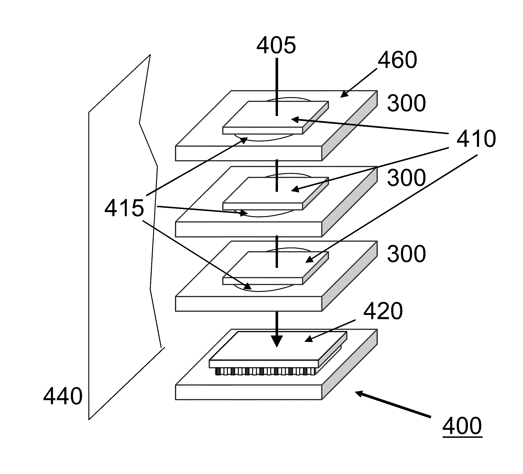
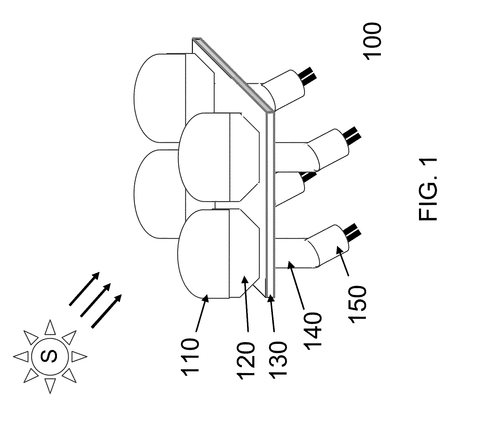
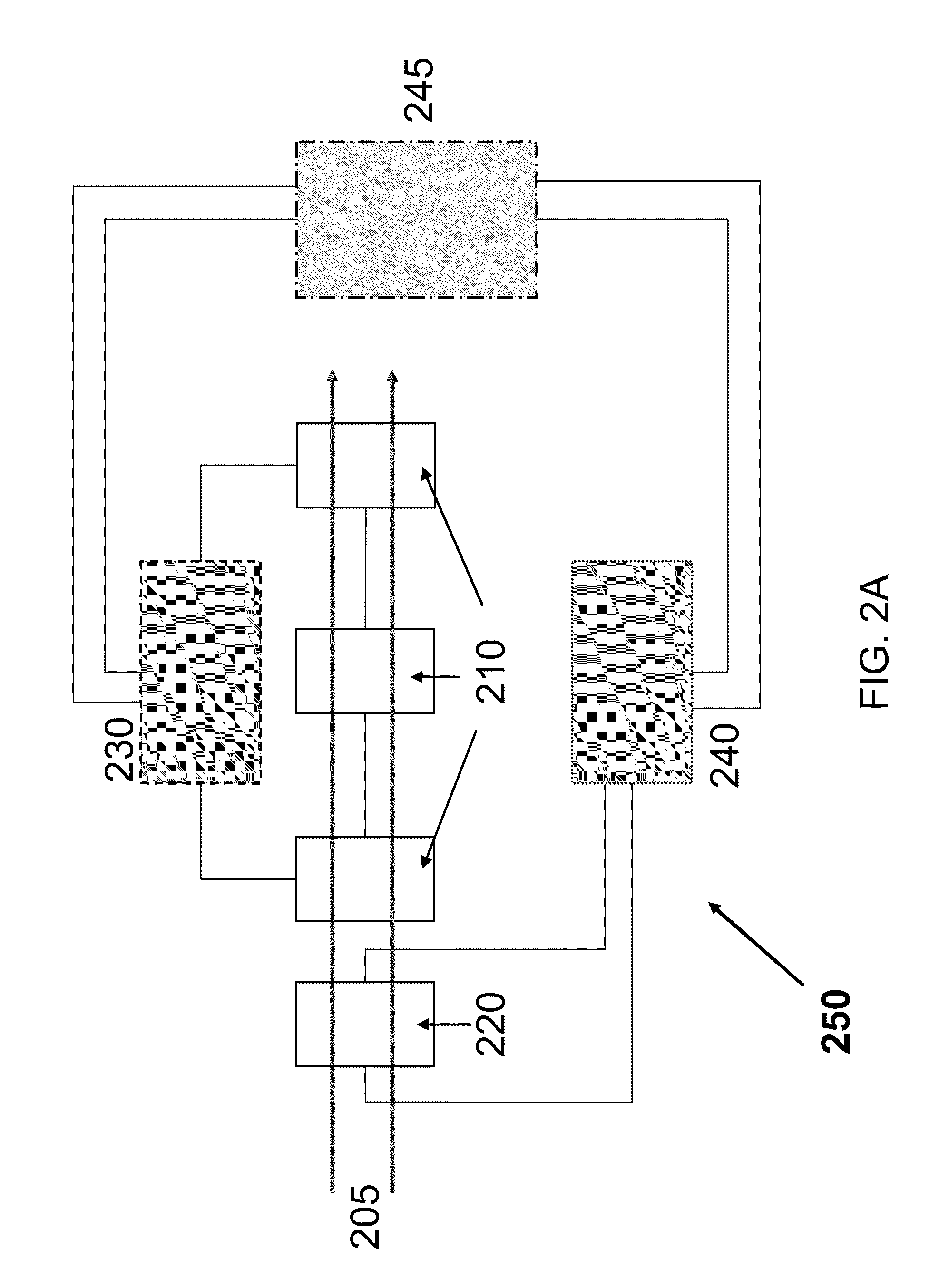
[0063]A novel modular platform integrates solid-state photovoltaic and thermionic or thermoelectric devices with the solar collection and concentration optics for the solar-to-electricity conversion. Both the conversion efficiency and the heat handling capability under a focal area of high solar concentration are increased by cascading photon-to-electricity devices such as photovoltaic devices and heat-to-electricity devices such as solid-state thermionic and thermoelectric devices, each of which is made of specific composition.

[0064]Embodiments of the present invention thus provide a conversion system that is scalable for the photovoltaic device of area from a few hundreds of micron square to a few tens of centimeter square with the corresponding optical collection area that gives a concentration factor from 250× to 5,000×. The overall conversion efficiency of the solid-state solar engine module of the present invention has potential to achieve 50% or more of which the conversion f...


PUM


Abstract

The invention addresses the area utilization and capital efficiency of systems for converting solar energy into electricity. A solid-state solar submodule includes photovoltaic and thermoelectric or thermionic cells. The submodule can be implemented in various configurations and by a solar insolation flux collection and concentration method to improve the area utilization and solar-to-electricity conversion efficiency. A thermal expansion matched multilayer board is also used to withstand ultra high concentration of solar insolation flux.

Description

FIELD OF THE INVENTION[0001]The present invention relates to the field of solar electricity and, more particularly, to the collection and conversion of solar energy into electricity using submodules that use concentrated solar flux / insolation, and which can be assembled into larger solar energy conversion systems.BACKGROUND[0002]The collection of solar energy including photonic and thermal energies within the solar spectrum and subsequent conversion to electric power have been explored for many applications including, but not limited to, photovoltaics, concentrating photovoltaics, thermophotovoltaics, solar thermal power, concentrating solar thermal power, active solar heating, and passive solar heating, cooling, solar thermo-electrochemical, and daylighting. In solar collection, there are a number of optical systems demonstrated for long-term reliability such as flat-plates, flat-plates with side reflectors, tubular collectors, paraboloids, parabolic troughs, Fresnel lens or reflec...

Claims


Application Information

Patent Timeline
IPC IPC(8): H01L31/058H01L31/052
CPCH01L31/052H01L35/30H05K1/0203H05K1/0274H05K1/0298H05K2201/09072H01L31/0547Y02B10/14Y02B10/20Y02B10/70Y02E10/52H02S10/10H01L31/0543H05K2201/10121H02S40/44Y02E10/60Y02B10/10H10N10/13
Inventor PAN, ERIC TING-SHAN
Owner PAN ERIC TING SHAN
Why Eureka
Try Eureka