Production Method for Molded Coil

a production method and technology of molded coils, applied in the direction of encapsulation/impregnation, inductance, other domestic articles, etc., can solve the problems of air-core coils being likely to become deformed, air-core coils being likely to be deviated from the intended position, etc., to achieve the effect of enhancing the positional accuracy of air-core coils, facilitating the production of molded coils, and high degree of molding accuracy

Inactive Publication Date: 2009-10-08
TOKO KABUSHIKI KAISHA
View PDF3 Cites 34 Cited by
  • Summary
  • Abstract
  • Description
  • Claims
  • Application Information

AI Technical Summary

Benefits of technology

[0014]In the molded coil production method of the present invention, the positioning pin is moved to the given retracted position thereof in the course of the charging of the moldable magnetic resin material into the cavity This makes it possible to encapsulate the air-core coil with the moldable magnetic resin material in a stepwise manner while keeping the air-core coil in the intended position.
[0015]In the molded coil production method of the present invention, an air-core coil having an inner peripheral surface with a non-generally circular shape may be used. In this case, the air-core coil can be kept from being rotated within the cavity. This makes it possible to more enhance positional accuracy of the air-core coil. The non-generally circular shape may be one selected from the group consisting of a semicircu...

Problems solved by technology

In the conventional molded coil production method, if it is tried to encapsulate an air-core coil with a moldable magnetic resin material in an independent state without using a magnetic core, various problems are likely to arise.
For example, the air-core coil is likely to become deformed due to a charging pressure of the moldable magnetic resin material.
Moreover, the air-core coil is likely to become deviated from an intended position due to displacement or inclination toward one side of the cavity.
However, the magnetic core or the frame used in conventional molded coils hinders a reduction in overall size or height dimension of...

Method used


Image

  • Production Method for Molded Coil
  • Production Method for Molded Coil
  • Production Method for Molded Coil

Examples


first embodiment

[0048]With reference to FIGS. 1 to 4, a molded coil production method according to a first embodiment of the present invention will be described.

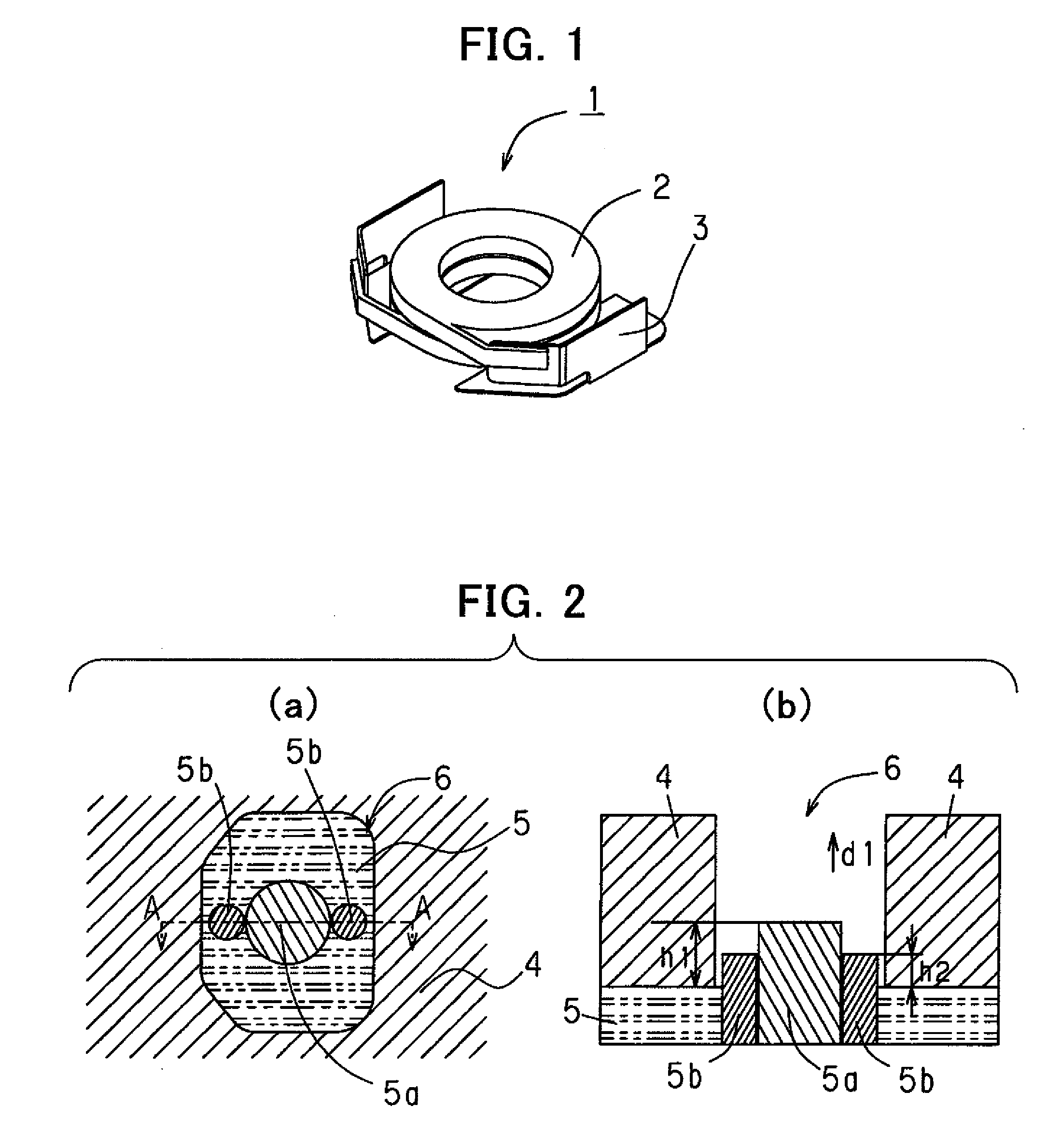
[0049]A coil member for use in the method according to the first embodiment will first be described below. FIG. 1 is a perspective view showing a coil member 1 for use in the method according to the first embodiment. As shown in FIG. 1, the coil member 1 comprises an air-core coil 2 and an external electrode 3. The air-core coil 2 is formed using a self-bonding rectangular wire having a width of 0.25 mm and a thickness of 0.06 mm. The air-core coil 2 is obtained by using a core having a diameter of 1.0 mm, and by winding the rectangular wire swirlingly by 12 turns in two stages. The air-core coil 2 is formed such that both ends become outermost peripheries. Then, the air-core coil 2 is spot-welded to the external electrode 3 to obtain the coil member 1 illustrated in FIG. 1. The external electrode 3 may be made of phosphor bronze or electro...

second embodiment

[0057]With reference to FIGS. 5 and 6(d), a molded coil production method according to a second embodiment of the present invention will be described. The method according to the second embodiment is intended to produce a molded coil having the same configuration as that of the molded coil in the first embodiment, by a transfer molding process using the same coil member and moldable magnetic resin material as those used in the first embodiment. Thus, the method according to the second embodiment employs a common element to that in the first embodiment, and a detailed description about such a common element will be omitted.

[0058]A molding die assembly designed for a transfer molding process in the method according to the second embodiment will first be described below. FIG. 5 is a fragmentary sectional view showing a molding die assembly for use in the method according to the second embodiment. As shown in FIG. 5, the molding die assembly designed for a transfer molding process in th...

third embodiment

[0064]With reference to FIGS. 7 to 11(d), a molded coil production method according to a third embodiment of the present invention will be described. Differently from the first and second embodiments, the method according to the third embodiment employs a molding die assembly having only a positioning pin without any support pin. Further, the method according to the third embodiment is characterized in that an external electrode is attached to an air-core coil in such a manner as to allow the air-core coil to be held in midair within the molding die assembly. The method according to the third embodiment employs a common element to that in the first or second embodiment, and a detailed description about such a common element will be omitted.

[0065]A coil member for use in the method according to the third embodiment will first be described. FIG. 7 is a perspective view showing an external electrode for use in the method according to the third embodiment, and FIG. 8 is a perspective vi...


PUM

PropertyMeasurementUnit
Percent by volumeaaaaaaaaaa
Pressureaaaaaaaaaa
Moldableaaaaaaaaaa

Abstract

Disclosed is a method oft by using a plastic molding process, encapsulating an air-core coil with a moldable magnetic resin material prepared by kneading a mixture of a magnetic powder and a resin. The method comprises the steps of (a) preparing a molding die assembly which includes a plurality of dies adapted to define a cavity therewithin, and a positioning pin adapted to be movable in a vertical or horizontal direction within the cavity, (b) arranging the air-core coil at a given position within the cavity by the positioning pin, (c) charging the moldable magnetic resin material into the cavity and moving the positioning pin to a given retracted position in a course of the charging.

Description

BACKGROUND OF THE INVENTION[0001]1. Field of the Invention[0002]The present invention relates to a production method for a molded coil, and more particularly to a method for encapsulating an air-core coil with a moldable magnetic resin material.[0003]2. Description of the Background Art[0004]Heretofore, a molded coil has been widely used which has a coil encapsulated with a moldable magnetic resin material prepared by kneading a mixture of a magnetic powder and a resin. A conventional molded coil production method comprises setting a coil wound around a magnetic core, such as a ferrite core, within a cavity of a die assembly, and then charging a moldable magnetic resin material in a molten state, into the cavity to encapsulate the coil therewith. JP 04-338613A and JP 2006-032847A disclose a molded coil production method using a magnetic core.[0005]In the conventional molded coil production method, if it is tried to encapsulate an air-core coil with a moldable magnetic resin material...

Claims


Application Information

Patent Timeline
IPC IPC(8): B29C45/14
CPCB29C43/18B29C43/36B29C45/02B29C45/14073B29C2043/3618B29K2303/06H01F2017/048B29L2031/3061B29L2031/711H01F27/027H01F41/005H01F41/127H01F2017/046B29K2995/0008
Inventor FUKUI, YOSHIZUMI
Owner TOKO KABUSHIKI KAISHA
Why Eureka
Try Eureka