Optical nonlinear evaluation device and optical switching element

a nonlinear evaluation and optical switching technology, applied in the direction of optical apparatus testing, optical radiation measurement, instruments, etc., can solve the problems of inability to use high-speed switching for quantum information processing, theoretical loss, and the inability to spatially sort the signal beams into either output port of a polarization beam splitter

Inactive Publication Date: 2009-10-08
JAPAN SCI & TECH CORP
View PDF3 Cites 10 Cited by
  • Summary
  • Abstract
  • Description
  • Claims
  • Application Information

AI Technical Summary

Benefits of technology

[0012]Further, the above-described arrangement of the measurement system in which the normal Sagnac interferometer is used observes the phase difference between the clockwise and counterclockwise signal beams by converting the phase difference into light intensity. This causes a reduction in detection sensitivity in a small phase shift region.
[0037]Therefore, the control beam is separated from either of the second and third signal beams having traveled through the Kerr medium, the linearly-polarized beam emitted to different ports in accordance with whether or not the control means allows the control beam to be supplied. This makes it possible to provide a two-input and two-output optical switching element for use in high-speed switching for the purpose of quantum information processing that operates at a high speed by femtosecond pulses.

Problems solved by technology

This causes such a problem that the optical nonlinear evaluation device described in Non-patent Document 1 causes a theoretical loss and cannot be used for high-speed switching for the purpose of quantum information processing.
From the viewpoint of switching, this causes such a problem that a polarization rotation caused by cross-phase modulation makes it impossible to spatially sort the signal beams into either output port of a polarization beam splitter without losing the signal beams.

Method used


Image

  • Optical nonlinear evaluation device and optical switching element
  • Optical nonlinear evaluation device and optical switching element
  • Optical nonlinear evaluation device and optical switching element

Examples


embodiment 1

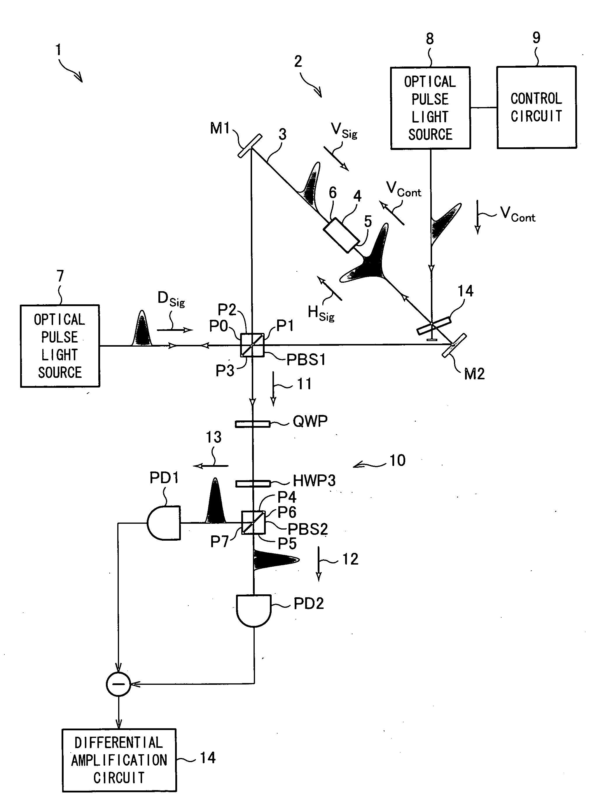
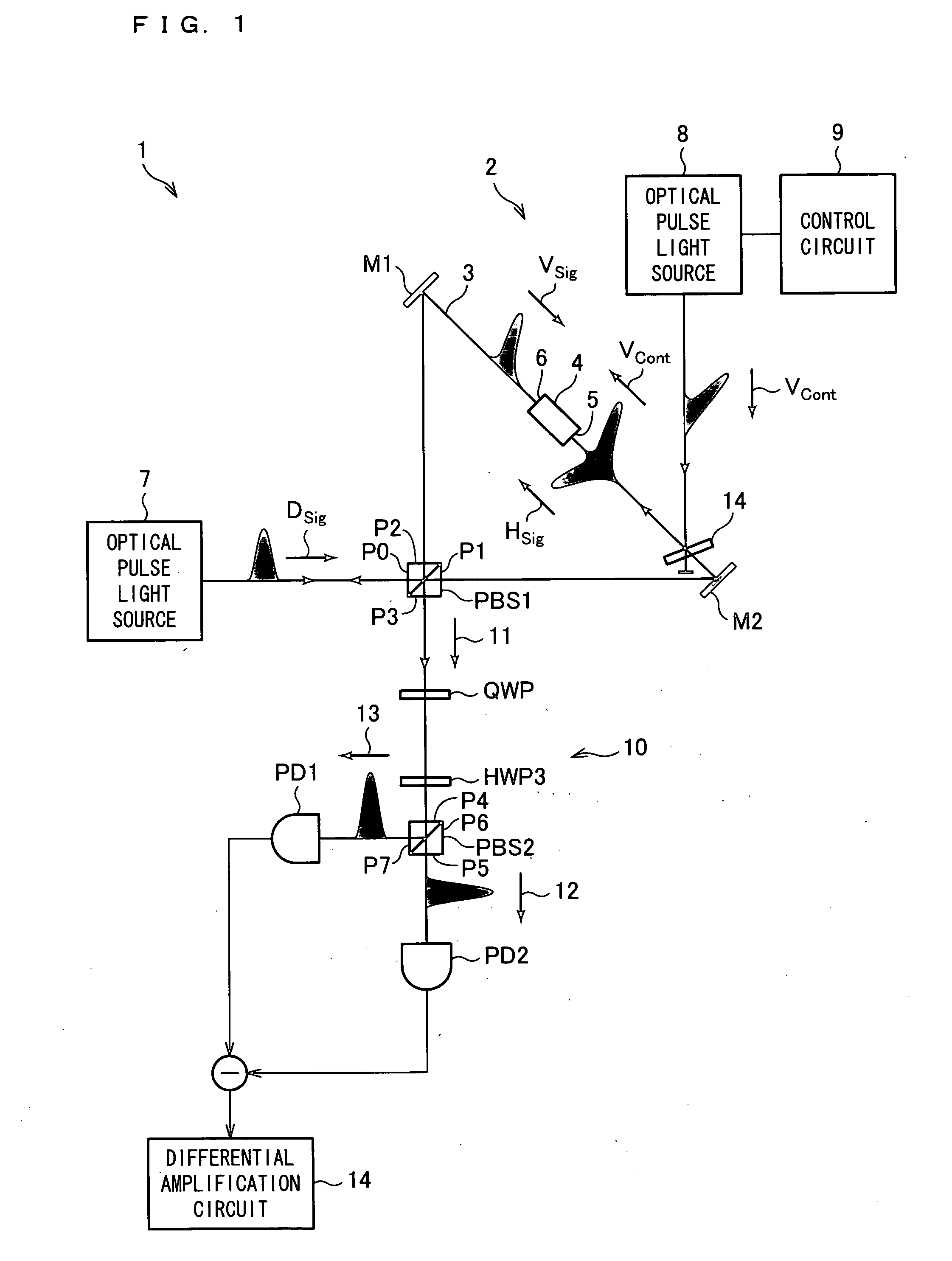
[0073]FIG. 1 is a block diagram showing an arrangement of an optical nonlinear evaluation device 1 according to Embodiment 1. The optical nonlinear evaluation device 1 includes a polarization Sagnac interferometer 2. The polarization Sagnac interferometer 2 is provided with a polarization beam splitter PBS1. The polarization beam splitter PBS1 has ports P0, P1, P2, and P3. The ports P0 and P1 are formed so as to be opposite each other, and the ports P2 and P3 are formed so as to be opposite each other.

[0074]The polarization Sagnac interferometer 2 has a mirror M1 and a mirror M2. The mirror M1 is disposed so as to face the port P2, and the mirror M2 is disposed so as to face the port P1. The polarization beam splitter PBS1 and the mirrors M1 and M2 form a triangular polarization Sagnac interference optical path 3.

[0075]Disposed in the middle of the space between the mirror M1 and M2 is a Kerr medium 4 that causes an optical nonlinear effect of causing a change in refractive index in...

embodiment 2

[0117]FIG. 4 is a block diagram showing an arrangement of an optical nonlinear evaluation device 1a according to Embodiment 2. Those components identical to the aforementioned components are given the identical reference numerals, and will not be fully described below.

[0118]In Embodiment 2, the control beam Vcont and the signal beam Hsig have different wavelengths. Since the optical nonlinear evaluation device 1a according to Embodiment 2 distinguishes between the control beam Vcont and the signal beam Hsig by wavelength, the control beam Vcont may be polarized in any direction.

[0119]The optical nonlinear evaluation device 1a includes a polarization Sagnac interferometer 2a. The polarization Sagnac interferometer 2a has a dichroic mirror DM1 provided between the Kerr medium 4 and the mirror M2. The dichroic mirror DM1 completely transmits the signal beam Hsig and completely reflects the control beam Vcont supplied from the optical pulse light source 8, thereby coaxially superimposin...

embodiment 3

[0125]FIG. 5 is a block diagram showing an arrangement of an optical nonlinear evaluation device 1b according to Embodiment 3. Those components identical to the aforementioned components are given the identical reference numerals, and will not be fully described below.

[0126]In Embodiment 3, the control beam Vcont and the signal beam Hsig are polarized in directions that differ by 90 degrees from each other. The control beam Vcont and the signal beam Hsig may have identical wavelengths.

[0127]The optical nonlinear evaluation device 1b includes a polarization Sagnac interferometer 2b. The polarization Sagnac interferometer 2b has: a Faraday unit FU1, disposed between the Kerr medium 4 and the mirror M2, which has a Faraday rotator FR1 and a half-wave plate HWP1; and a Faraday unit FU2, disposed between the Kerr medium 4 and the mirror M1, which has a Faraday rotator FR2 and a half-wave plate HWP2.

[0128]The polarization Sagnac interferometer 2b has: a polarization beam splitter PBS3 pro...


PUM

PropertyMeasurementUnit
transmittanceaaaaaaaaaa
reflectanceaaaaaaaaaa

Abstract

An optical nonlinear evaluation device (1) capable of accurately evaluating the optical nonlinearity of a Kerr medium in accordance with a phase difference caused by cross-phase modulation generated in the Kerr medium includes: a polarization Sagnac interference path (3) provided with a Kerr medium (4); an optical pulse light source (7) for supplying a signal beam (Dsig); a polarization beam splitter (PBS1) for splitting the signal beam (Dsig) into a signal beam (Hsig) and a signal beam (Vsig) polarized in a direction orthogonal to the signal beam (Hsig), for supplying the signal beam (Hsig) to a first side of the Kerr medium (4), and for supplying the signal beam (Vsig) to a second side of the Kerr medium (4); a glass plate (14) for entering, onto the signal beam (Hsig), a control beam (Vcont) for causing a change in phase difference between the signal beam (Hsig) and the signal beam (Vsig); separating means for separating the control beam (Vcont) from the signal beam (Hsig) having traveled through the Kerr medium (4); and a detection section (10) provided so as to detect the phase difference between the signal beam (Hsig) and the signal beam (Vsig).

Description

TECHNICAL FIELD[0001]The present invention relates to an optical nonlinear evaluation device and an optical switching element each of which uses a polarization Sagnac interferometer to detect, as polarization information, a phase shift caused by cross-phase modulation generated in a Kerr medium.BACKGROUND ART[0002]Conventionally, there have been used optical nonlinear evaluation devices (e.g., see Non-patent Document 1 and Patent Document 1) each of which uses a polarization Sagnac interferometer to detect, as polarization information, a phase shift caused by cross-phase modulation of a signal beam by irradiating, with a control beam, a Kerr medium that causes an optical nonlinear effect of causing a change in refractive index in accordance with light intensity.[0003]According to the optical nonlinear evaluation device described in Non-patent Document 1, a waveguide Kerr medium such as an optical fiber is disposed on a polarization Sagnac interference path of a polarization Sagnac i...

Claims


Application Information

Patent Timeline
Patent Type & Authority Applications(United States)
IPC IPC(8): G01C19/72G02F1/025G01J9/02G01M11/00G02B27/28G02F1/35G02F1/383
CPCG01J9/02G02F1/3519G02F1/3511
Inventor EDAMATSU, KEIICHISHIMIZU, RYOSUKEMATSUDA, NOBUYUKI
Owner JAPAN SCI & TECH CORP
Why Eureka
Try Eureka