Method of configuring power tool electronics in a hand-held power tool

a technology of power tools and electronics, which is applied in the direction of specific program execution arrangements, program control, wireless commuication services, etc., can solve the problem that the tool only permits a manual transmission of data, and achieve the effect of simple manner

Active Publication Date: 2009-10-08
HILTI AG
View PDF4 Cites 71 Cited by
  • Summary
  • Abstract
  • Description
  • Claims
  • Application Information

AI Technical Summary

Benefits of technology

[0019]It is further advantageous when, in addition to the control parameters, control programs and / or control program parts can be transmitted from the evaluation location to the data transmission unit with the configuration file so that it is possible to adapt and / or upgrade the control program in a simple manner.
[0020]Further, it is advantageous when a position determining device for global positioning is provided in addition to the data transmission unit, wherein the position data determined by the position determining device are transmitted by the data transmission unit along with the data transmission to the evaluation location. As a result of this step, the data to be sent by the data transmission unit is supplemented by a position indicator for the current location of the power tool, which is particularly advantageous for preventing theft. Further, certain data such as, e.g., ambient temperature data, can be related to the position and geography of the area in which the power tool is used.

Problems solved by technology

It is disadvantageous that the power tool only permits a manually controlled transmission of data when the power tool is located in the immediate vicinity of a personal computer.

Method used


Image

  • Method of configuring power tool electronics in a hand-held power tool
  • Method of configuring power tool electronics in a hand-held power tool
  • Method of configuring power tool electronics in a hand-held power tool

Examples


Embodiment Construction

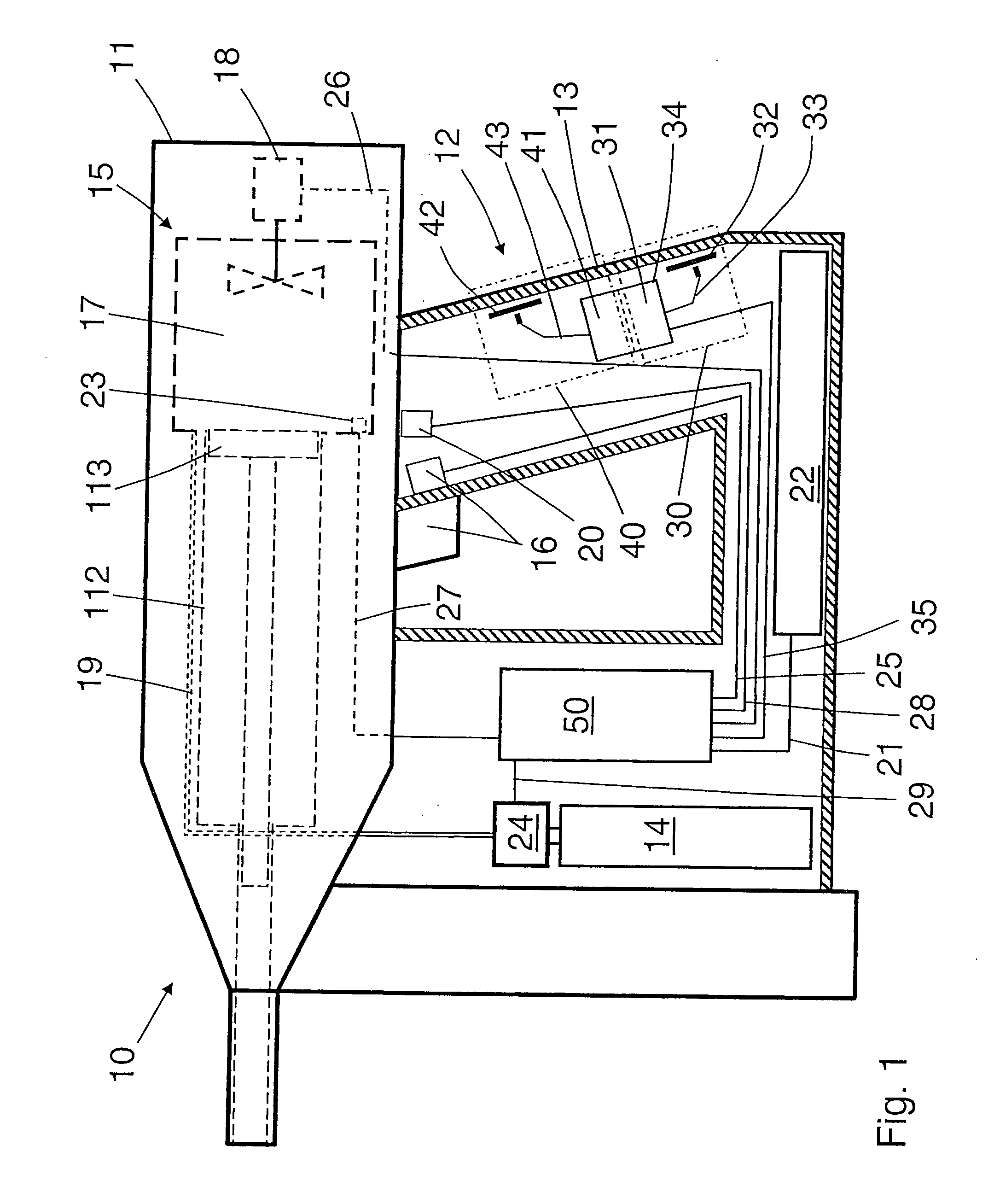
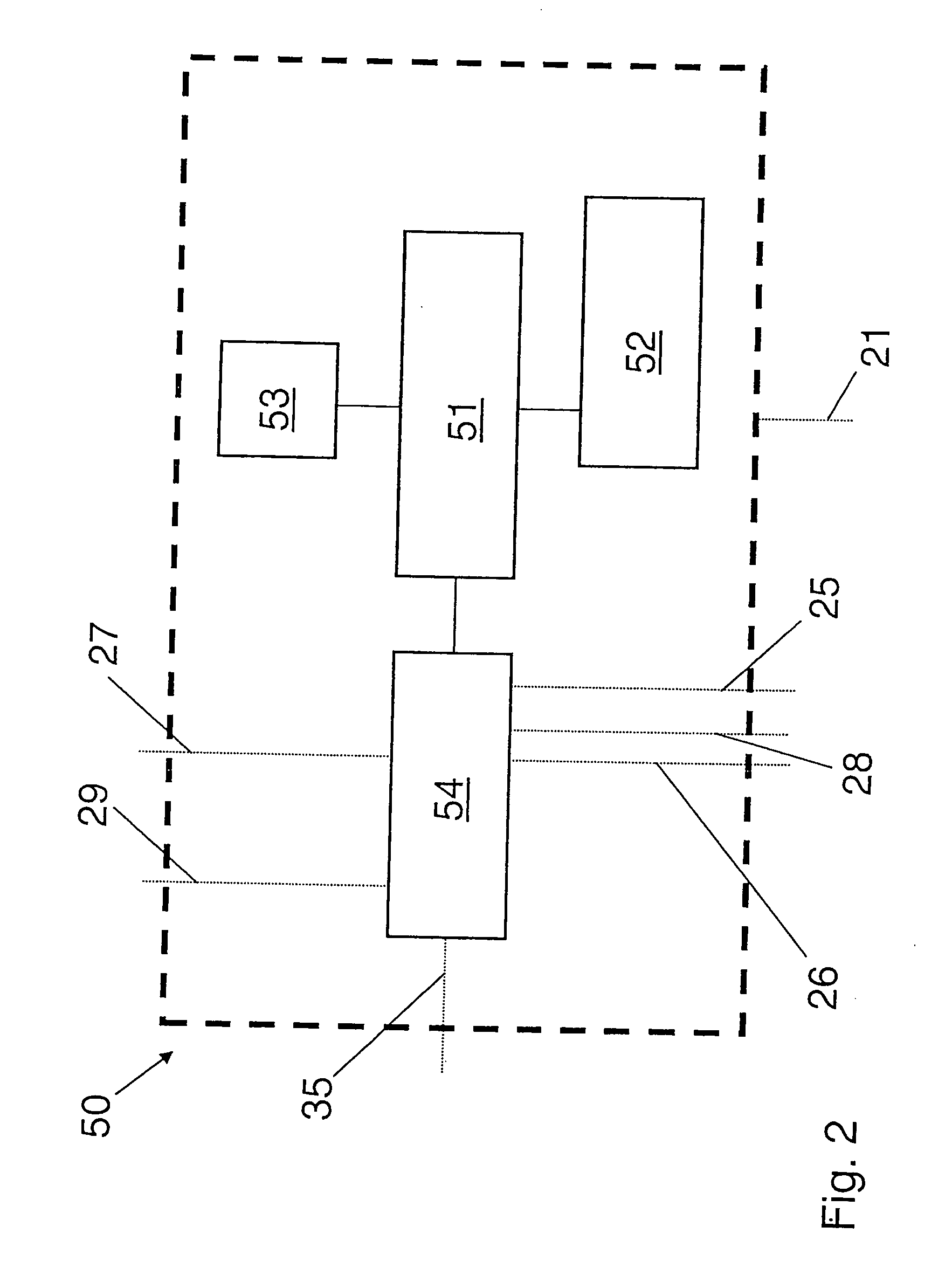
[0027]FIGS. 1 and 2 show a hand-held power tool 10 according to the invention in the form of a combustion-powered fastener setting power tool. The power tool 10 has a housing, designated generally by 11, which is formed of one or more parts and in which a drive 15 is arranged. A fastening element such as a nail, bolt, etc. can be driven into a workpiece by means of the drive 15. The fastening elements can be stored, for example, in a magazine at the power tool 10.

[0028]The drive includes a combustion chamber 17 and a guide cylinder 112 in which a setting piston 113 is arranged so as to be axially displaceable. As can further be seen from FIG. 1, a trigger switch 16 is arranged at a handle area 12 of the power tool 10 by which can actuate a firing power tool 23, e.g., a spark plug, in the combustion chamber 17 when the power tool 10 has been pressed against a workpiece. In addition to the trigger switch 16 mentioned above, additional switches such as, e.g., contact pressing switches,...


PUM


Abstract

A method of configuring power tool electronics in a hand-held power tool (10) having sensor means (20) for acquiring measurement data, a control unit (50) for processing measurement data and for controlling power tool functions, and a data transmission unit (30), includes transmitting data between the data transmission unit (30) and an evaluation location (62) by means of a mobile wireless network, with the power tool electronics being awakened from a quiescent mode (70) and activated at a time stored as a time parameter in a control program, retrieving a configuration file provided by the evaluation location (62) by the data transmission unit (30) via the mobile wireless network, and checking the response received from the mobile wireless network to determine whether or not it contains a new configuration file. If a configuration file was received, the parameters contained in the configuration file are implemented (77) in the control program for the power tool electronics. The power tool electronics is then returned to the quiescent mode (70) again.

Description

BACKGROUND OF THE INVENTION[0001]1. Field of the Invention[0002]The present invention is directed to a method of configuring a data transmission unit in a hand-held power tool including sensors for acquiring measurement data, a control unit for processing the measurement data and for controlling power tool functions, and a data transmission unit.[0003]2. Description of the Prior Art[0004]Hand-held power tools can be formed, e.g., as fastener driving power tools which are operated electrically or with solid, gaseous, or liquid fuels or also with compressed air. Hand-held power tools of this kind can also be formed as rotary or at least partially percussive hand-held power tools such as, e.g., hammer drills or chisel power tools. Other examples of such power tools include drilling machines, drill hammers, demolition hammers, screw driving power tools, grinding saws, circular saws, chain saws, and saber saws. The data transmission unit is arranged either in the power tool itself or in ...

Claims


Application Information

Patent Timeline
Patent Type & Authority Applications(United States)
IPC IPC(8): G05B19/04G01S5/00G01S19/04G01S19/10G01S19/44G01S19/46G06F9/44G06F15/16
CPCB25C1/08G01S5/0027G01S19/39H04L41/082H04L67/12H04W52/0212H04L41/0869Y02D30/70
Inventor GEROLD, UWEKECK, JOACHIMWELTE, NORBERT
Owner HILTI AG
Why Eureka
Try Eureka