Optical Absorption Spectrometer and Method for Measuring Concentration of a Substance

a technology of absorption spectrometer and concentration measurement, which is applied in the direction of optical radiation measurement, interferometric spectrometry, instruments, etc., can solve the problems of substantially all the radiation absorbed by the gas molecules, the signal output of the cips is saturated and will not respond properly, and the measurement range of the instrument is inherently limited, so as to increase the concentration range across which the assembly can generate accurate measurements, reduce the dependence of the concentration signal on the incident radiation intensity

Inactive Publication Date: 2009-10-15
BAH HLDG
View PDF12 Cites 15 Cited by
  • Summary
  • Abstract
  • Description
  • Claims
  • Application Information

AI Technical Summary

Benefits of technology

[0019]The provision of first and second optical paths in this way enables the spectrometer to be used for accurate measurement of both low and high gas concentrations. At low gas concentrations, the longer optical path provides high sensitivity, whereas at high concentrations the shorter optical path contains relatively few gas molecules such that a measurement can still be taken. The signal received by the detector assembly is effectively a superposition of the radiation received along each optical path. There may of course be any number of different optical paths through the sample, provided there are at least two.
[0052]Preferably, the sample to be measured is contained within a cavity, at least one radiation path passing through the cavity. It is further advantageous to provide first and second radiation paths as specified by the first aspect of the invention in order to further broaden the concentration range of the instrument.

Problems solved by technology

One problem frequently encountered in many types of optical absorption spectrometer, including NDIR devices and CIPS apparatus, is that the measurement range of the instrument is inherently limited.
For concentrations above its designed range, the signal output by the CIPS saturates and will not respond properly.
The disadvantage of using a long optical path is that, in the presence of higher gas concentrations, substantially all the radiation is absorbed by the gas molecules before it can reach the detector (in accordance with Beer's law).
As such, it is not presently possible to use a single apparatus for the accurate measurement of high gas concentrations as well as low gas concentrations.
The problem is also made worse by the dependence of the measured radiation signal on uncontrollable measurement conditions.
For example, factors such as dust occurring in the optical system or radiation beam misalignment, etc., can decrease the incident radiation intensity, leading to an erroneous concentration measurement.

Method used


Image

  • Optical Absorption Spectrometer and Method for Measuring Concentration of a Substance
  • Optical Absorption Spectrometer and Method for Measuring Concentration of a Substance
  • Optical Absorption Spectrometer and Method for Measuring Concentration of a Substance

Examples


first embodiment

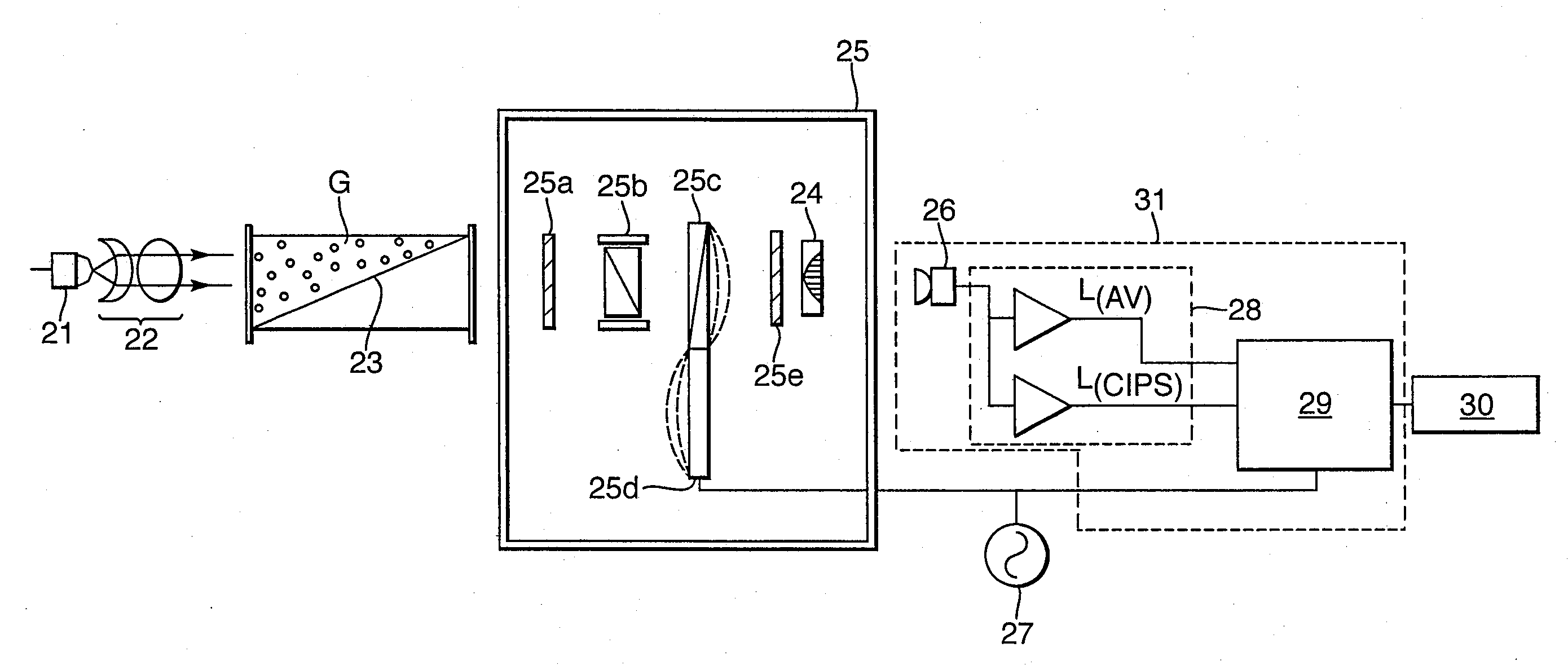
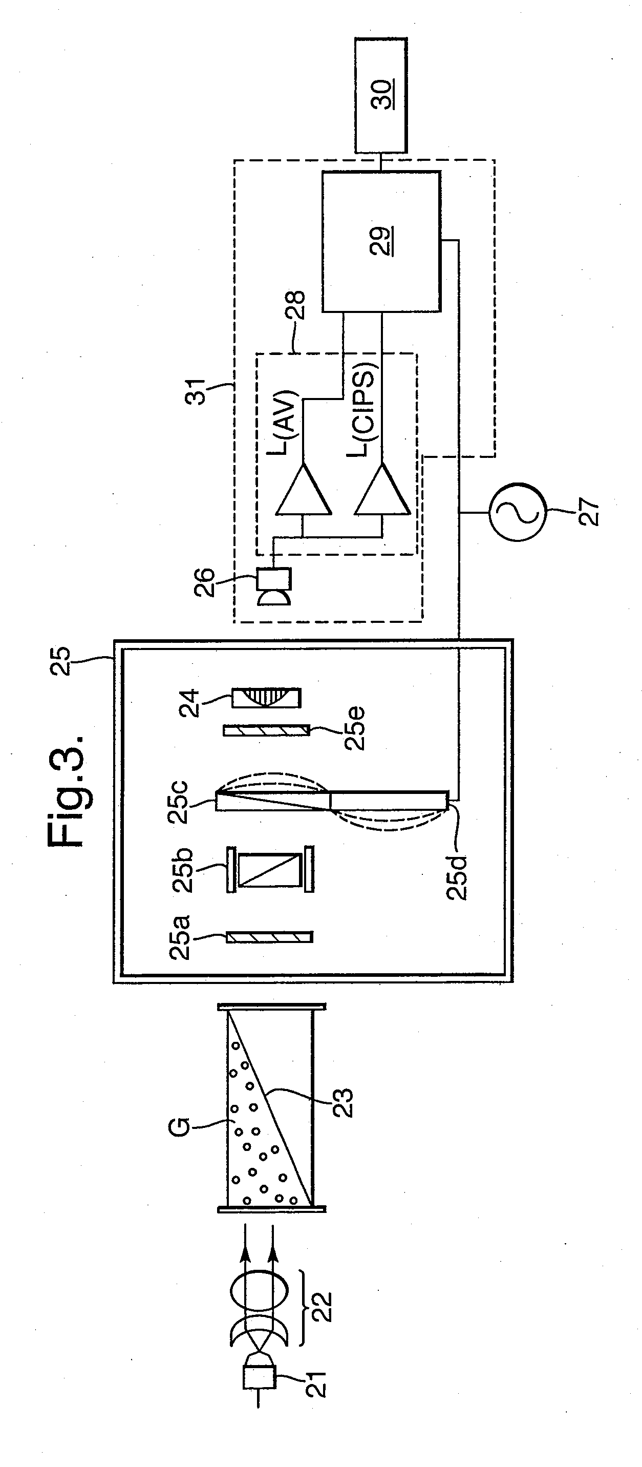
[0086]FIG. 3 shows the present invention, which is a CIPS having a modified gas cavity 23. The remaining components shown in FIG. 3 largely correspond to the FIG. 2 example.

[0087]A radiation source 21 such as a lamp, LED or laser, generates a radiation beam which is collimated by collimator 22 to pass through cavity 23 containing gas G which is the sample to be measured. Radiation transmitted by the gas G passes to the controlled interference polarization filter (cIPF) section 25. Here, the cIPF is shown to comprise two polariser elements 25a and 25e either side of an etalon 25b and a crystal 25c which exhibits induced birefringence. The birefringence is induced by a piezoelectric driver 25d supplied from an AC voltage 27 and synchronised with the processor 29.

[0088]In this example, the last component of cIPF 25 is a bandpass filter 24 which corresponds in function to filter 14 shown in FIG. 2.

[0089]Radiation transmitted by the cIPF 25 is detected by detector assembly 31 which compr...

second embodiment

[0091]A simpler example of a suitable gas cavity used in the invention is shown in FIG. 4. Here, the cavity 32 is defined between walls 33a and 33b of a chamber which comprises means for varying the cavity dimensions in the form of a partition 34 dividing off a volume containing radiation-transparent material T. The walls 33a and 33b and the partition 34 are all substantially transparent to the radiation, at least in the vicinity of the radiation beam(s) passing therethrough. The radiation transparent material T may be a solid material (e.g. it could be a continuation of the wall 33B or the partition 34), or it could be an inert gas such as nitrogen, i.e. one which does not absorb the radiation. The presence of volume T effectively causes the cavity dimension parallel to the radiation beam to vary along a perpendicular direction in a stepwise manner.

[0092]For clarity, FIG. 4 does not show the surrounding components of the spectrometer (which could be a CIPS or NDIR spectrometer, for...

third embodiment

[0097]FIG. 5 shows another cavity for use in an absorption spectrometer. As in the embodiment of FIG. 3, here the cavity 40 has a triangular cross-section.

[0098]The cavity 40 is defined within a chamber having walls 41a and b and a partition 42 creating a sample-free volume of radiation transparent material T. As in the example of FIG. 4, any radiation transparent material could be used, but nitrogen is particularly preferred. The partition 40 could be fixed or could be movable by a user such that the dimensions of the cavity 40 could be adjusted according to the measurement conditions.

[0099]As in FIG. 4, the three radiation rays AA′, BB′ and CC′ are depicted. In this example, each of the paths traverses a different distance through the sample gas G since the dimension of the gas cavity 40 varies continuously from top to bottom. In this case, the variation is linear whereas in other cases any other function e.g. curved, sinusoidal or parabolic could be used instead.

[0100]Again, this...


PUM

PropertyMeasurementUnit
lengthaaaaaaaaaa
lengthaaaaaaaaaa
optical absorption spectrometeraaaaaaaaaa

Abstract

An optical absorption spectrometer is provided for determining the concentration of a substance within a sample. The optical absorption spectrometer comprises a first radiation source for supplying radiation to the sample to be measured; at least one cavity for containing the sample during measurement; and a detector assembly for detecting radiation transmitted along first and second optical paths through the sample, the length of the first optical path being greater than that of the second optical path.

Description

TECHNICAL FIELD[0001]The present invention relates to an optical absorption spectrometer for determining the concentration of a substance within a sample, and in particular for the optical detection of gases.BACKGROUND OF THE INVENTION[0002]A number of optical gas detection techniques exist and are based on the measurement of the absorption of incident radiation by the gas molecules. For example, non-dispersive infrared (NDIR) spectroscopy involves using a detector to monitor radiation transmitted by a sample when exposed to a radiation source. By measuring the radiation absorbed by the sample within a particular wavelength range, the concentration of a target gas in the sample can be determined.[0003]As explained in WO-A-01 / 65219 and WO-A-01 / 40748, another known type of optical absorption gas detector is the correlated interference polarisation spectrometer (CIPS). A CIPS works on the principle that for any given wavelength incident radiation, the quantity that is absorbed by the g...

Claims


Application Information

Patent Timeline
Patent Type & Authority Applications(United States)
IPC IPC(8): G01J3/45G01N21/00
CPCG01J3/42G01J3/457G01N2021/317G01N21/31G01N21/0303
Inventor TKACHUK, MICHAEL
Owner BAH HLDG
Why Eureka
Try Eureka