
System and method for treating fly ash

a technology of fly ash and treatment fluid, applied in sustainable waste treatment, process and machine control, instruments, etc., can solve the problems of fly ash, adverse effect of variation in fly ash carbon, and detrimental impact on concrete air entrainment, etc., to improve the mixing and interaction of the treatment fluid.

Inactive Publication Date: 2009-10-15
BORAL MATERIAL TECH
View PDF29 Cites 15 Cited by
  • Summary
  • Abstract
  • Description
  • Claims
  • Application Information

AI Technical Summary

Benefits of technology

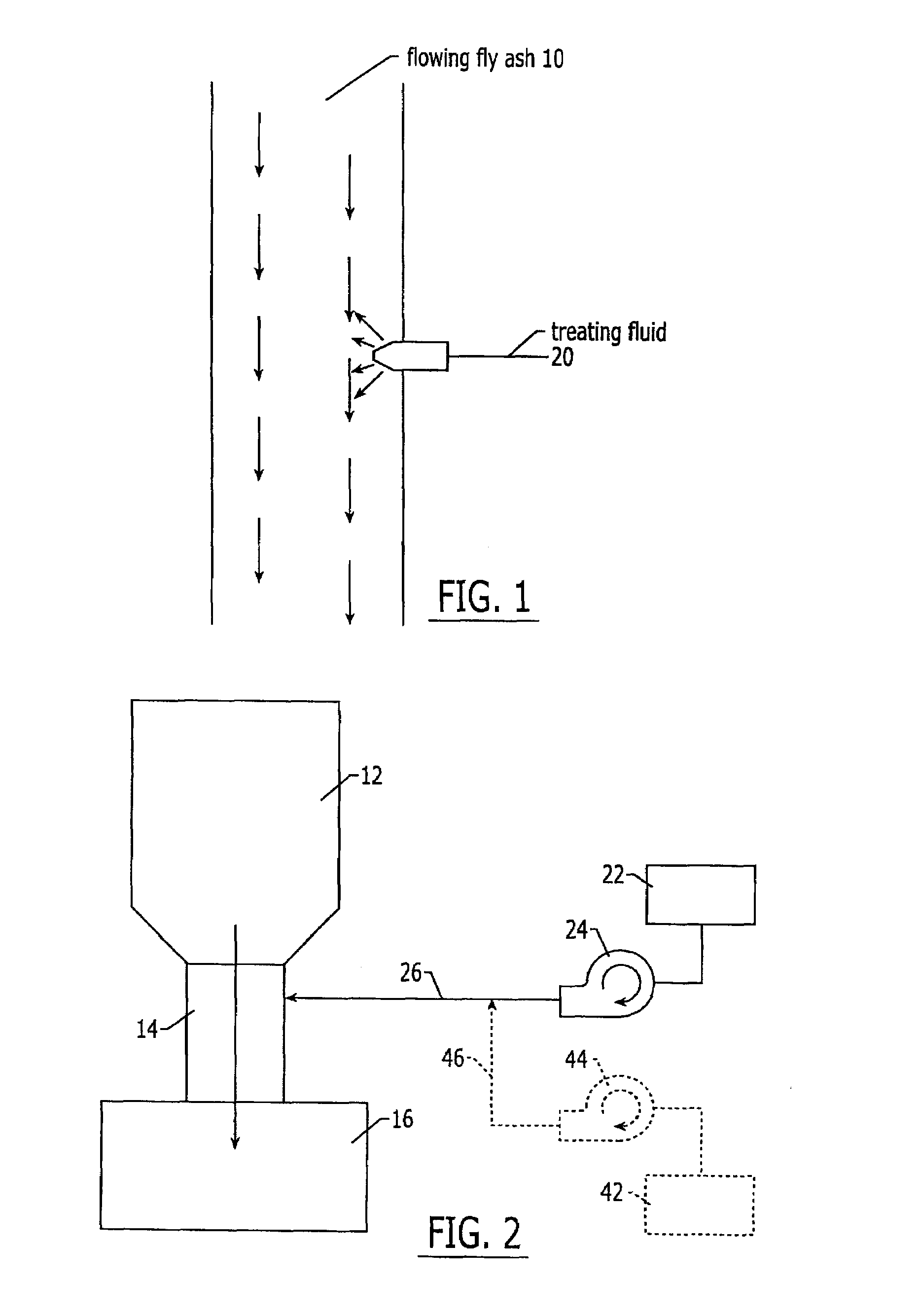
[0009]The invented method and system provides an improved manner of combining fly ash and a liquid such that the liquid is well dispersed within the fly ash and available to react with the fly ash or to coat the fly ash particles. The invention accomplishes this combination by evenly dispersing a treating fluid into a flowing stream of fly ash. By dispersing the treating fluid into the fly ash as the fly ash is flowing, the method takes advantage of natural mixing and particle motion that occurs during flow of the bulk solid. Further, when the fly ash freely flows, either by gravitational free fall or pneumatic conveyance, the fly ash exhibits flow characteristics of a fluid. Treatment of the fly ash when fluidized further improves the mixing and interaction of the treating fluid with the ash.
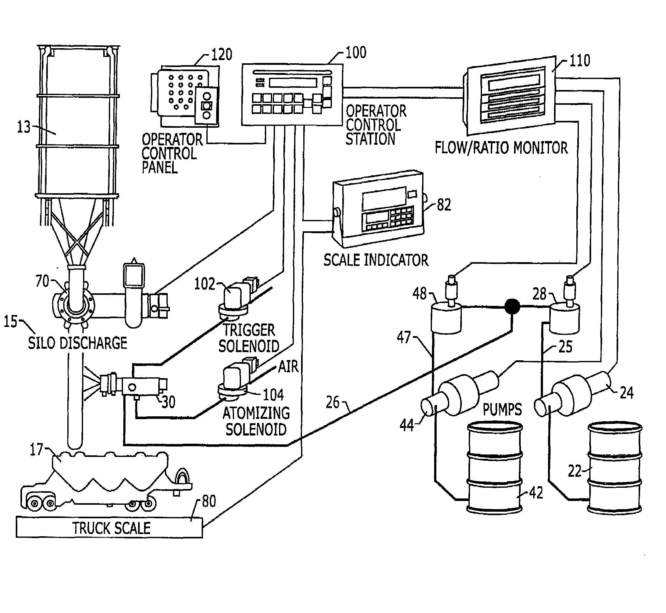
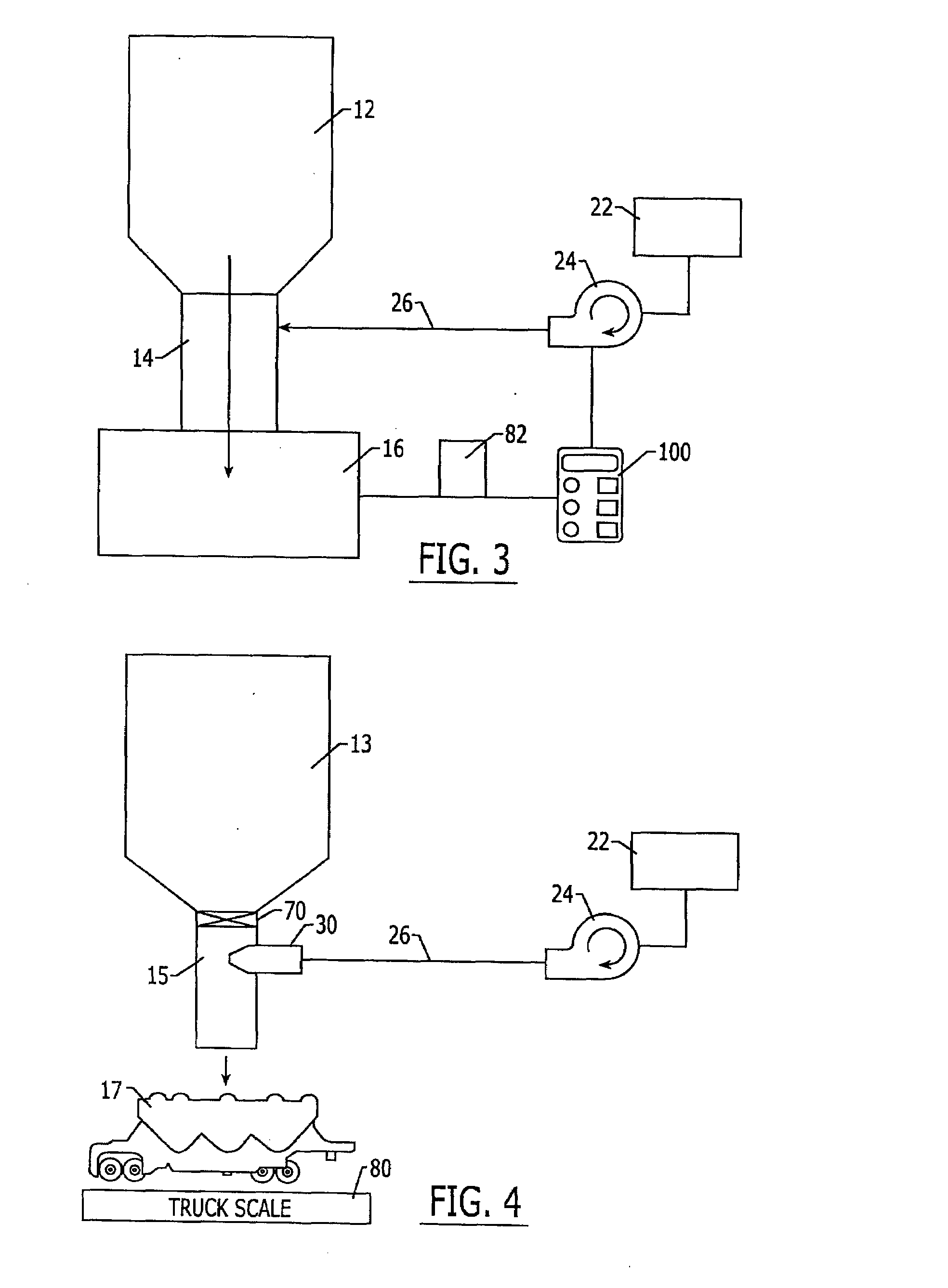
[0011]According to another embodiment of the invention, the fly ash treatment system is a stand alone system that is attachable to a preexisting fly ash storage system. A typical preexisting fly ash storage system has a silo with a silo discharge and a silo discharge valve, a container loading station positioned under the silo discharge, and a scale for weighing the container. The system for attachment to the silo station includes a treating fluid supply, such as a tank, a treating fluid supply line leading from the treating fluid supply, a device or apparatus for pressurizing the treating fluid, and a nozzle at the end of the treating fluid supply line opposing the fluid supply for receiving fluid and dispersing the fluid. The system also includes an automated controller with multiple inputs and outputs, with at least one output operatively connected to the pressurizing device for control of the treating fluid flow rate. The system may be easily installed upon the silo station by positioning the nozzle of the system within the wall of the silo discharge, operatively connecting the silo discharge valve to an output of the controller, and operatively connecting the scale, perhaps through a scale indicator, to an input of the controller.
[0013]Several advantages are obtained by treating the fly ash while flowing through a silo discharge or other conduit already necessary in the transfer of fly ash. Only minimal modifications need to be made to previously existing silos in order to convert the silos into treating stations. By disposing the fluid discharge nozzles within the silo discharge, and making a few electrical connections between the controller of the system and the operating controls of the silo, the system is easily installed.
[0014]The system is a economical system that may be added to preexisting silos without the need for additional capital equipment or expensive modifications to existing equipment.

Problems solved by technology

Though fly ash provides favorable cement characteristics when added to concrete, the fly ash, or more specifically fly ash carbon (often indexed by loss on ignition) can have a detrimental impact on air entrainment in concrete.
Variation in fly ash carbon have a particularity detrimental effect because of the difficulty in determining a correct dosage of chemical air entraining admixture for a specified air volume as the carbon content fluctuates.
The micron-sized particles of the fly ash present special problems in mixing the ash with the treating liquids.
The small particle size makes it difficult to disperse the treating liquid among the particles.
Combination of the treating liquid and ash in a tumbler or similar mixing device is somewhat ineffective due to clumping of the fly ash material.
More complex mixing devices provide adequate mixing, but at added capital expense.

Method used


Image

  • System and method for treating fly ash
  • System and method for treating fly ash
  • System and method for treating fly ash

Examples


Embodiment Construction

[0022]The present invention now will be described more fully hereinafter with reference to the accompanying drawings, in which some, but not all embodiments of the invention are shown. Indeed, these invention may be embodied in many different forms and should not be construed as limited to the embodiments set forth herein; rather, these embodiments are provided so that this disclosure will satisfy applicable legal requirements. Like numbers refer to like elements throughout.

[0023]Referring to FIG. 1, the invented system and method supplies a stream of treating fluid 20 and disperses the treating fluid 20 into a stream of flowing fly ash 10 in order to intimately mix the fly ash and treating fluid, thereby allowing the treating fluid 20 to coat the fly ash 10 or to better react with components of the fly ash 10. Freely flowing fly ash flows in a fluid-like state and is readily mixed with material introduced into the flowing stream. By introducing the treating fluid 20 into the fluid-...


PUM

PropertyMeasurementUnit
Massaaaaaaaaaa
Weightaaaaaaaaaa
Pressureaaaaaaaaaa

Abstract

A method and system for treating fly ash with a treating fluid by evenly dispersing a treating fluid into a flowing stream of fly ash. By dispersing the treating fluid into the fly ash as the fly ash is flowing, the method takes advantage of natural mixing and particle motion that occurs during flow of the bulk solid. The application of treating fluid is advantageously controlled by an automated controller that has inputs and outputs that allow the controller to adjust flow rate of the treating fluid in correspondence with a measured flow rate of the fly ash.

Description

BACKGROUND OF THE INVENTION[0001]The invention is generally related to a method and apparatus for combining the particulate components of fly ash with a treating fluid. Particularly, the invention provides the controlled addition of a fluid treating material to a bulk fly ash material.[0002]Fly ash is a fine, glass-powder recovered from the gases of burning coal during the production of electricity. The micron-sized fly ash particles consist primarily of silica, alumina, and iron, and may contain various other oxides and residual carbon.[0003]Fly ash has a number of uses as an additive for different materials. For instance, when mixed with lime and water the fly ash forms a cementitious composition with properties very similar to that of portland cement. Because of this similarity, fly ash can be used to replace a portion of cement in concrete. Also, because fly ash consists of very small particulates, the ash may advantageously be used as a filler in plastics.[0004]In the formation...

Claims


Application Information

Patent Timeline
IPC IPC(8): C03C3/04G05D24/00C04B18/08
CPCC04B18/08C04B2111/1087C04B2111/1093C04B20/02C04B20/023C04B20/10Y02W30/91B29B7/905B09B3/00B01F23/51
Inventor TARDIF, MARC-ANDREMAJORS, RUSS K.HILL, RUSSELL L.
Owner BORAL MATERIAL TECH
Learn More