
Method of construction for solar energy systems

a technology of solar energy and solar energy, applied in the direction of heat collector mounting/support, building repair, lighting and heating apparatus, etc., can solve the problems of limited range of motion, tracking apparatus not being able to address all arbitrary points in the sky, and limited range of desired orientations

Inactive Publication Date: 2009-10-22
SUNPOWER CORPORATION
View PDF16 Cites 24 Cited by
  • Summary
  • Abstract
  • Description
  • Claims
  • Application Information

AI Technical Summary

Problems solved by technology

Practically speaking, mechanical considerations can limit the range of motion such that the tracking apparatus might not be able to address all arbitrary points in the sky.
However, in many applications, such as solar energy collection systems, the range of desired orientations is also limited to a subset of the visible sky.
As such, single axis tracking apparatuses, which are generally not capable of orienting the energy collection device perfectly normal to the solar radiation, are commonly used in solar PV systems.
Further, dual axis designs may not have the dynamic range required to address a large portion of the sky while maintaining the high accuracy required for high concentration PV modules or for telescope applications.
While these materials are sufficient for the application, there are several disadvantages to their use that are difficult to solve.
(a) Metals that are inherently corrosion resistant, such as aluminum or stainless steel are generally expensive.
As such, use of such materials can negatively impact the economics of a particular installation.
(b) While carbon steel is less expensive than aluminum or stainless steel, it subject to corrosion under normal atmospheric conditions.
However, the galvanizing process increases the cost of the raw material significantly.
Furthermore, the galvanizing process is generally considered to be environmentally hazardous, and as such the number of domestic suppliers has been in recent decline.
The optimization of materials tends to lead to mounting apparatus structure designs that are often complex.
The manufacturing processes required to build components for complex systems are generally not suitable for performance in the field.
This can result in increased shipping costs.
As stated previously, higher shipping costs can be a disadvantage of using precast elements, but the optimal solution is typically determined based on project specifics.
However, prior art is limited to use of precast foundation blocks, that were cast in a mold and then moved to the installation location.
Note that there is no prior art for either the use of precast concrete components in the moving part of a tracking mounting system, nor is there any prior art showing the use of tilt-up construction methods, wherein a component is cast in a substantially horizontal orientation and then erected into a non-horizontal orientation.

Method used


Image

  • Method of construction for solar energy systems
  • Method of construction for solar energy systems
  • Method of construction for solar energy systems

Examples


first embodiment

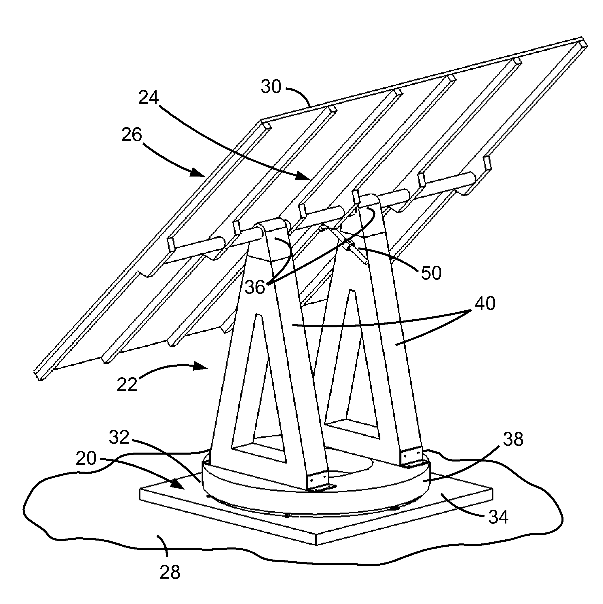
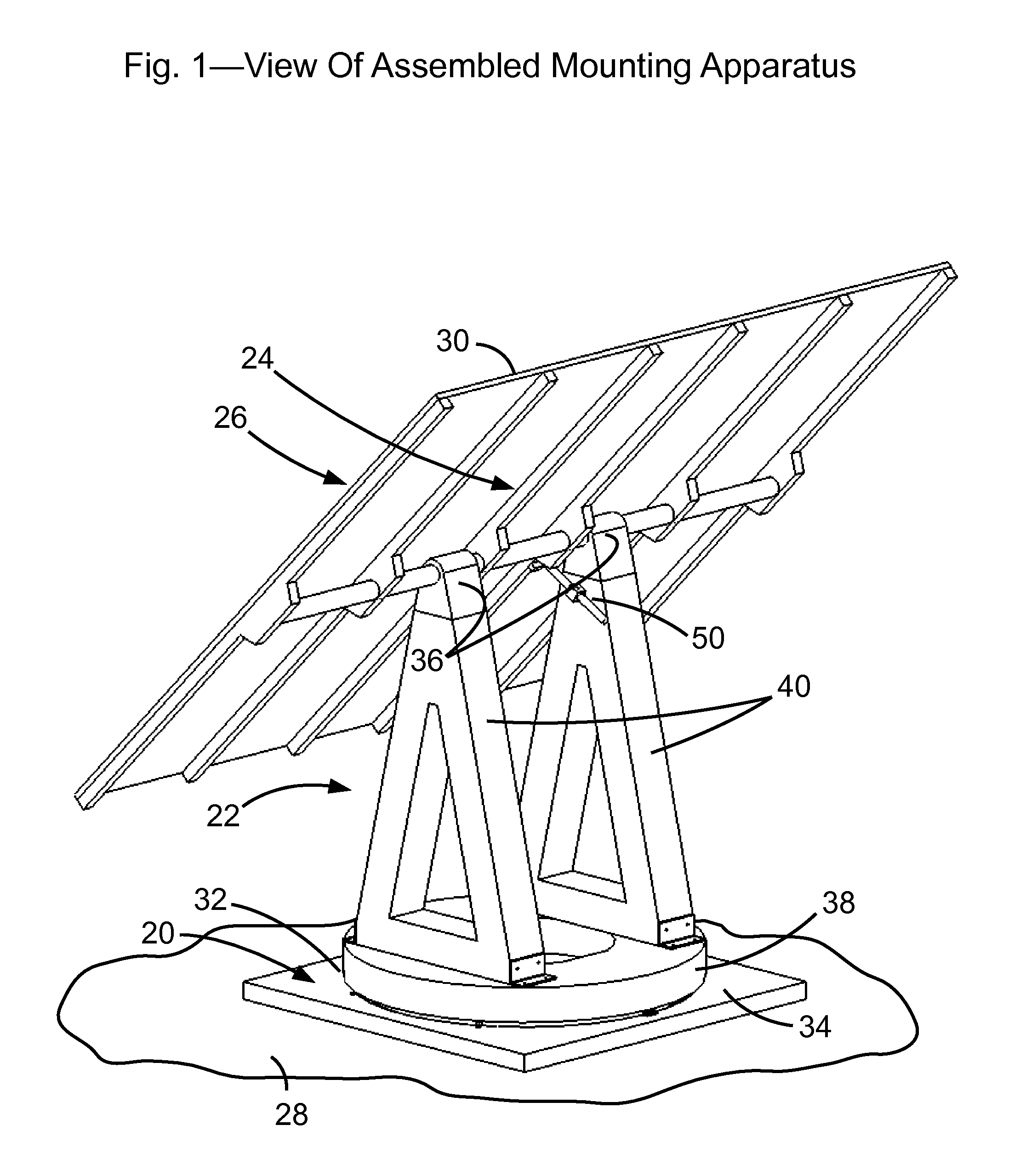
[0040]In a first embodiment, the method is shown as applied to the construction of an azimuth-elevation tracking solar energy mounting apparatus comprising a support 20, azimuth structure 22, an elevation structure 24, and a payload assembly 26. Support 20 is mounted on a mounting surface 28. payload assembly 26 is mounted on elevation structure 24. In this embodiment, mounting surface 28 is realized as the Earth. In other embodiments, mounting surface 28 could be a separate structure, such as a the roof of a dwelling. In this embodiment, payload assembly 26 comprises an array of flat plate PV module 30. In other embodiments, payload assembly 26 could be realized as any device or structure that captures, reflects, refracts, or interacts with electromagnetic energy, or any combination thereof.

[0041]In the first embodiment, support 20 comprises a concrete slab 34. Concrete slab 34 is mounted on mounting surface 28. Concrete slab 34 is pivotally coupled to azimuth structure 22 by an az...

second embodiment — figs 8-9

SECOND EMBODIMENT—FIGS 8-9

[0062]It is desirable to mold and pour azimuth ring 38 and each of azimuth truss 40 that will be assembled together in a single mounting apparatus at around the same time to allow all components to cure on approximately the same schedule and thus be ready for handling and assembly at approximately the same time. Because it can take days or weeks for concrete elements to cure sufficiently for safe handling, this means that molds for azimuth ring 38 and each of azimuth truss 40 should be constructed at the same time as well. However, depending on the relative size of concrete slab 34 compared to the area required for the three molds, there may not be enough room on concrete slab 34 to place and pour the molds on the same surface. In the second embodiment, the concrete elements are built in a stack such that both of partially cured top surface 72 of two of truss mold 74 serves to support bottom surface 44 of ring mold. More specifically, two of truss mold 74 a...

embodiments — figs 10-11

ADDITIONAL EMBODIMENTS—FIGS 10-11

[0067]In the first two embodiments, the molding and pouring process takes place on concrete slab 34 at the site where the mounting apparatus will be installed. However, in alternative embodiments, parts of the process can take place either at another location on the site or at a separate remote location.

[0068]In another embodiment, it could be advantageous to dry cast some or all of the concrete elements very early in the cure cycle. Dry casting refers to an embodiment of the process wherein azimuth ring 38 and / or each of azimuth truss 40 is partially removed from its mold extremely early in the cure cycle, even while the concrete is still in a fluid, albeit in a very stiff, highly viscous, or low slump, state. In this situation, the process is to first remove vertical mold surfaces, such as outer enclosing wall 48 and interior enclosing wall 52. Because the concrete is in a very stiff state, the concrete can maintain its shape without substantially ...


PUM


Abstract

The invention is a method for constructing solar energy mounting apparatuses in which structural elements of the apparatus are cast in molds formed on a substantially horizontal surface. A self curing compound, such as reinforced concrete, is used as the material for the structural elements. After curing for sufficient time to achieve strength necessary to allow for handling, the structural element is hoisted into place in a substantially non-horizontal position. Alternatively, the structural element may be used in the moving portion of a solar energy mounting apparatus that performs a tracking function. The use of reinforced concrete in the structural elements of solar energy mounting apparatuses allows for cost reduction over the prior art in that reinforced concrete is less expensive on a unit strength basis than other typical structural materials, such as steel and aluminum. Additional cost reduction is possible because the mass of the reinforced concrete structural elements offsets ballast material that would otherwise be necessary to increase the mass of the foundation to provide resistance to overturning forces due to wind.

Description

CROSS-REFERENCE TO RELATED APPLICATIONS [0001]None.FEDERALLY SPONSORED RESEARCH [0002]None.SEQUENCE LISTING [0003]None.BACKGROUND—FIELD OF INVENTION[0004]The present invention relates to methods of construction for solar energy systems, specifically low cost methods of construction for mounting apparatuses used in solar energy systemsBACKGROUND—PRIOR ART[0005]There is substantial prior art relating to the design and configuration of mounting apparatuses for solar energy systems. For example, U.S. Pat. No. 4,870,949 (Butler), U.S. Pat. No. 7,252,083 (Hayden), and U.S. Pat. No. 6,722,357 (Shingleton) all show different configurations of solar energy mounting apparatuses.[0006]These mounting apparatuses are generally designed to orient a payload, with respect to the sun. While many mounting apparatuses are designed to actively orient the payload with respect to the sun, others provide only a fixed orientation. For solar energy collection systems in general, the payload can be one of a ...

Claims

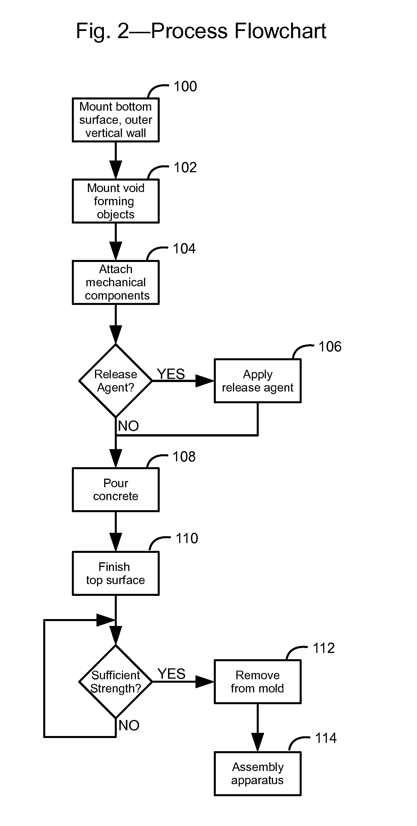

Application Information

Patent Timeline
Patent Type & Authority Applications(United States)
IPC IPC(8): F24J2/42E04B1/38F24S90/00
CPCB28B7/0029F24J2/5237F24J2/525Y02E10/47F24J2002/4687F24J2002/5281F24J2002/5292F24J2/541F24S2080/012F24S2025/014F24S25/11F24S30/425F24S25/617F24S2025/02
Inventor JONES, JASON CHARLESKRAFT, STEVEN MICHAEL
Owner SUNPOWER CORPORATION
Learn More