
Method for operating a gas turbine

a gas turbine and gas technology, applied in the direction of combustible gas production, lighting and heating apparatus, gasification process details, etc., can solve the problem of low exhaust gas value of sequential combustion system

Inactive Publication Date: 2009-10-22
GENERAL ELECTRIC TECH GMBH
View PDF4 Cites 13 Cited by
  • Summary
  • Abstract
  • Description
  • Claims
  • Application Information

AI Technical Summary

Benefits of technology

[0028]One of numerous aspects of the present invention includes a method for operating a gas turbine which operates together with a coal gasification plant and which can be characterized by a reduction of NOx emissions without noticeable loss of output and flexibility of operation.

Problems solved by technology

The low exhaust gas values of the sequential combustion system are produced as a result of the inherently low emission values which can be achieved in the case of reheating (under certain conditions the second combustion even leads to a consumption of NOx).

Method used


Image

  • Method for operating a gas turbine
  • Method for operating a gas turbine
  • Method for operating a gas turbine

Examples


Embodiment Construction

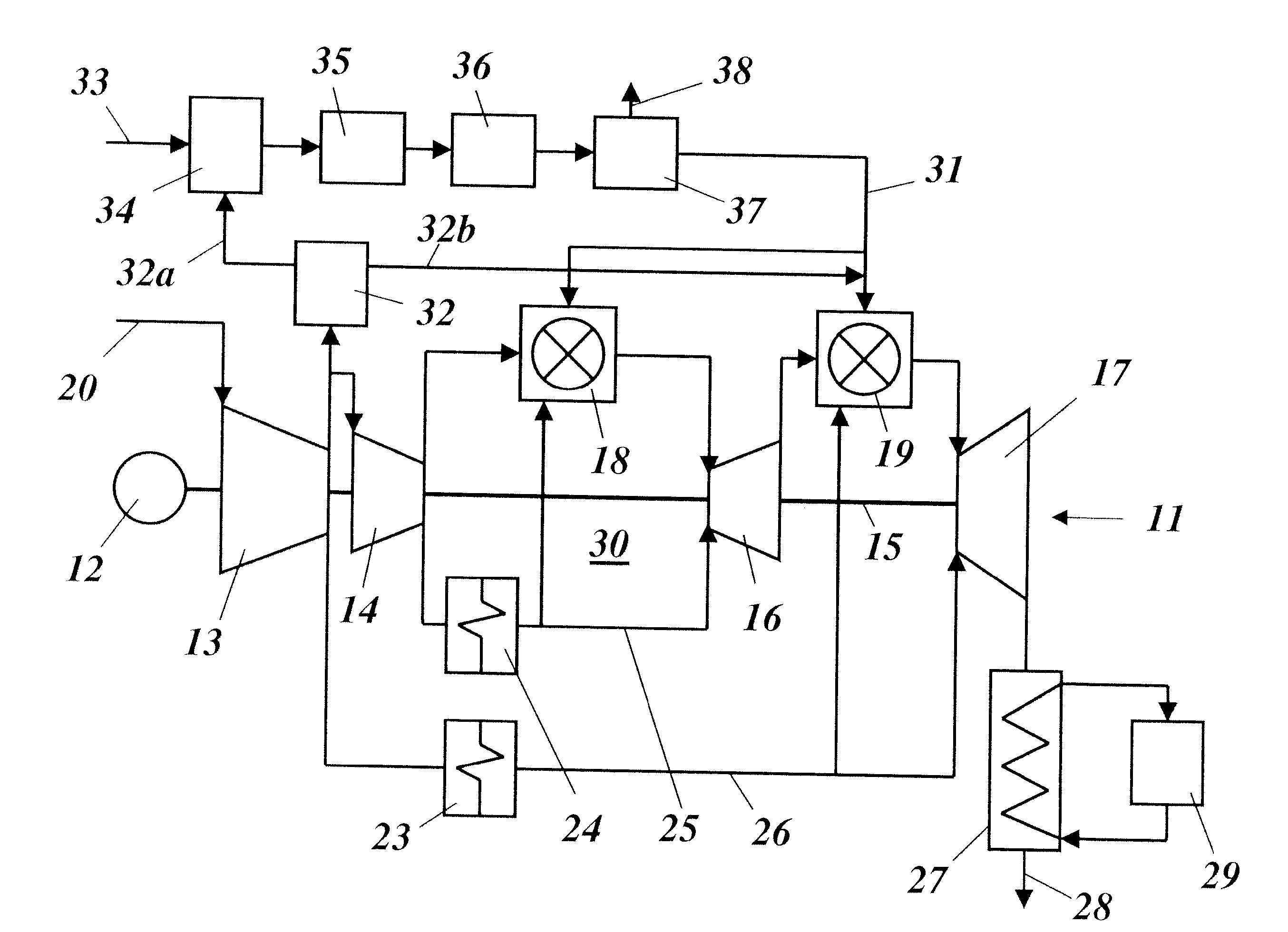
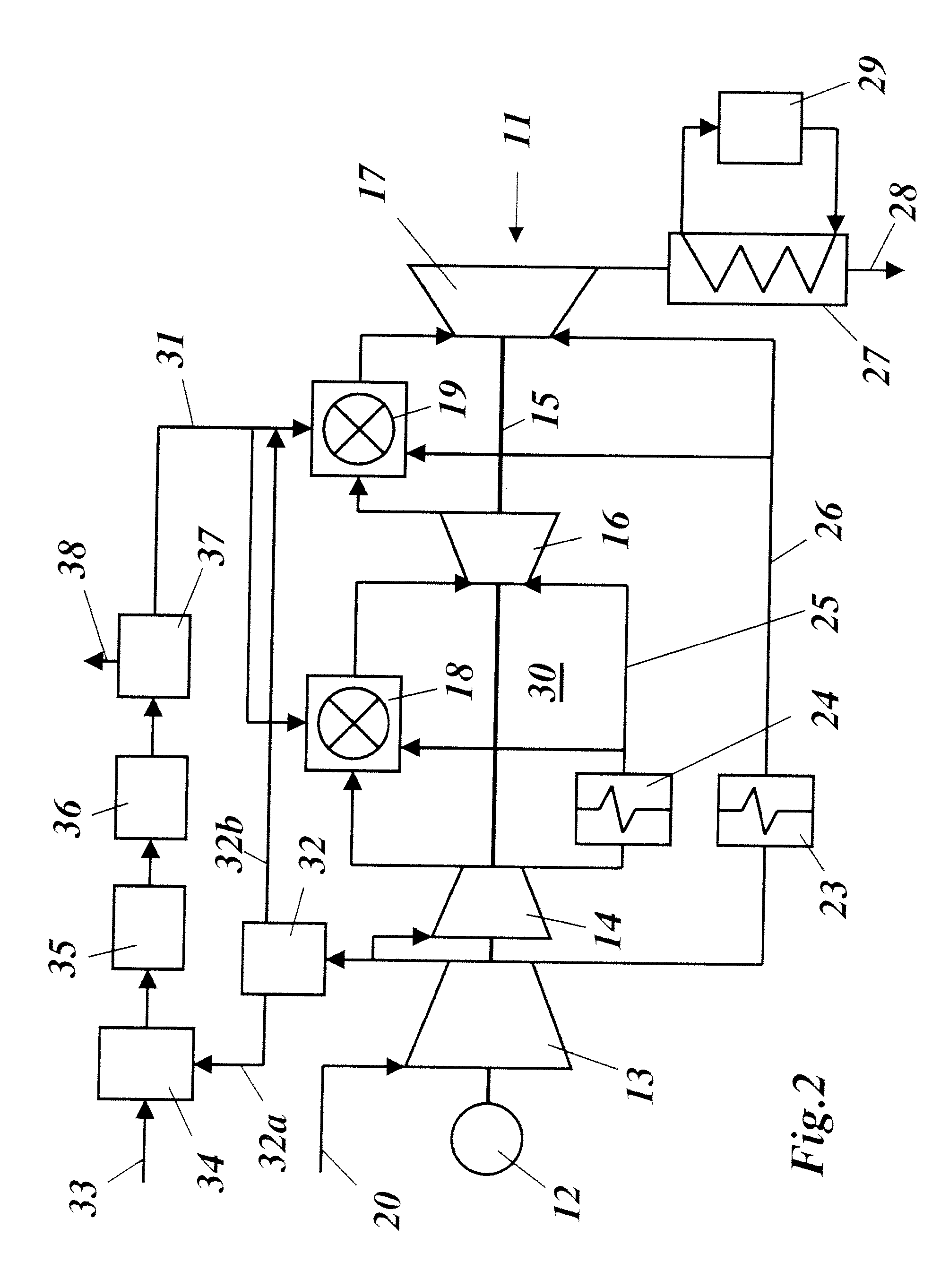
[0036]In FIG. 3, an IGCC plant with a gas turbine with reheating or sequential combustion, which is operated according to principles the invention, is shown in a much simplified schematic diagram. For like plant components, the same designations are used in this case, as in FIG. 2. The nitrogen (N2) which accumulates in the air separation unit 32 is no longer used here for dilution of the syngas which is used as fuel, but the syngas is injected into the combustors 18, 19 in an undiluted state. For this, in the first combustor 18 the flame temperature TF is lowered compared with the temperature TNG which prevails during normal natural gas operation, whereas in the second combustor 19 the nominal flame temperature TNG which is provided for natural gas operation is maintained. As a result of lowering the flame temperature in the first combustor 18, the production of NOx can be controlled without a crucial loss of output occurring. Thus, in the case of a gas turbine without reheating or...


PUM


Abstract

A method for operating a gas turbine (11), which is used especially in a combined-cycle power plant (30), includes inducting and compressing air by the gas turbine (11), the compressed air is fed to a combustor (18, 19) for the combustion of a syngas which is produced from coal, and the hot gases which result during the combustion are expanded in a subsequent turbine (16, 17), performing work, wherein some of the compressed air is separated into oxygen and nitrogen, and the oxygen is used in a coal gasification plant (34) for producing the syngas. With such a method, a reduction of the NOx emission is achieved without noticeable loss of output and flexibility of operation by a gas turbine (11) with reheating being used, which includes two combustors (18, 19) and two turbines (16, 17), wherein in the first combustor (18) syngas is combusted, using the compressed air, and the resulting hot gases are expanded in the first turbine (16), and wherein in the second combustor syngas is combusted, using the gases which issue from the first turbine (16), and the resulting hot gases are expanded in the second turbine (17), the two combustors (18, 19) are operated with undiluted syngas, and the flame temperature (TF) in the first combustor (18) of the gas turbine (11) is lowered compared with the operation with natural gas (TNG), while the second combustor (19) is operated largely in the normal operation (TNG) which is designed for natural gas.

Description

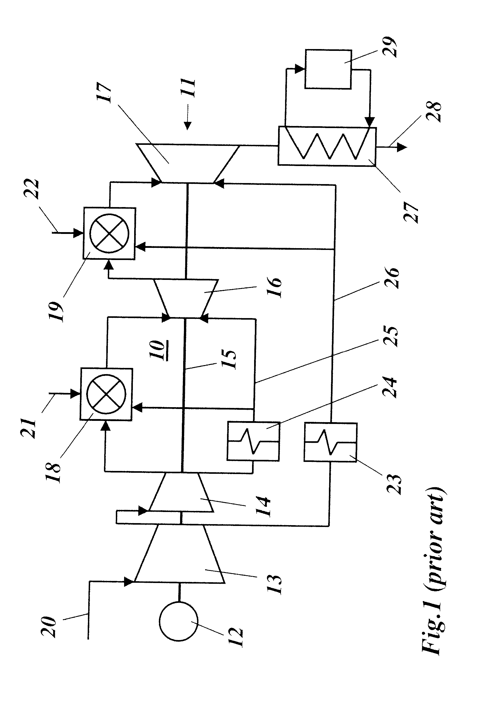
[0001]This application is a Continuation of, and claims priority under 35 U.S.C. § 120 to, International Application No. PCT / EP2007 / 062986, filed 29 Nov. 2007, and claims priority therethrough under 35 U.S.C. §§ 119, 365 to Swiss application no. 01956 / 06, filed 1 Dec. 2006, the entireties of both of which are incorporated by reference herein.BACKGROUND[0002]1. Field of Endeavor[0003]The present invention relates to the field of power plant technology. It refers to a method for operating a (stationary) gas turbine, and also to a gas turbine useful for carrying out the method.[0004]2. Brief Description of the Related Art[0005]A gas turbine with reheating (reheat gas turbine) is known (see, for example, U.S. Pat. No. 5,577,378, or “State-of-the-art gas turbines—a brief update”, ABB review 02 / 1997, FIG. 15, turbine type GT26), which combines a flexible operation with very low exhaust gas emission values.[0006]The machine architecture of gas turbine of type GT26 is uniquely and suitably ...

Claims


Application Information

Patent Timeline
Patent Type & Authority Applications(United States)
IPC IPC(8): F02C7/22
CPCC10J3/00Y02E20/16C10J2300/0959C10J2300/1606C10J2300/165C10J2300/1671C10J2300/1675C10J2300/1678C10J2300/1892F02C3/28F02C6/003F25J3/04545F25J3/04575Y02E20/18C10J2300/093
Inventor BENZ, ERIBERTFLOHR, PETEREROGLU, ADNANGUETHE, FELIXHELLAT, JAAN
Owner GENERAL ELECTRIC TECH GMBH
Learn More