Display device, vent tube with glass ring, phosphate glass ring, and method of producing the same

a technology of phosphate glass and display device, which is applied in the direction of gas-filled discharge tube, tube/lamp vessel exhaustion, and display device production using phosphate glass material, can solve the problems of difficult to extend the life of the display device produced using this glass ring, and difficult to completely prevent the exposed portion from coming into contact with the moisture in the outside air, so as to improve the long-term moisture resistance of the display device

Inactive Publication Date: 2009-10-22
PANASONIC CORP
View PDF1 Cites 8 Cited by
  • Summary
  • Abstract
  • Description
  • Claims
  • Application Information

AI Technical Summary

Benefits of technology

[0010]Therefore, even if a glass ring with a stepped portion formed therein, as shown in FIG. 7A, can be formed without any defect by using a phosphate glass material, it is not easy to extend the life of a display device produced using this glass ring. Since a glass member formed from a glass ring is exposed to the outside air, as shown in FIG. 7B, it is difficult to completely prevent the exposed portion from coming in contact with the moisture in the outside air. Therefore, the body of the glass member is eroded by moisture when it is made of a phosphate glass material, thereby causing a reduction in gas-tightness of a luminescence excitation space.
[0012]It is an object of the present invention to improve a long-term moisture resistance of a display device even though a phosphate glass is used as a material of a glass ring (glass member) to be used for mounting a vent tube on a panel. It is another object of the present invention to provide a vent tube with a glass ring, a phosphate glass ring, and a method of producing them, which are suitable for producing this display device.
[0018]According to the present invention, it is possible to prevent a glass member from coming in contact with the moisture in the outside air even though a phosphate glass is used as a material of a glass ring (the glass member) involved in mounting a tube on a panel, and thus to improve a long-term moisture resistance of a display device.

Problems solved by technology

It is difficult to enhance the water resistance of a glass ring made of a phosphate glass material up to a level of a glass ring made of lead glass.
Therefore, even if a glass ring with a stepped portion formed therein, as shown in FIG. 7A, can be formed without any defect by using a phosphate glass material, it is not easy to extend the life of a display device produced using this glass ring.
Since a glass member formed from a glass ring is exposed to the outside air, as shown in FIG. 7B, it is difficult to completely prevent the exposed portion from coming in contact with the moisture in the outside air.
According to the study of the present inventors, even if the load to be applied to both the panel and the vent tube for mounting the vent tube on the panel is increased close to the limit up to which a damage of the panel and the vent tube can be avoided, it is not easy to press down the stepped portion of the ring disposed between the end face of the vent tube and the panel so as to bring the end face of the vent tube close to the panel to the above-described extent.

Method used


Image

  • Display device, vent tube with glass ring, phosphate glass ring, and method of producing the same
  • Display device, vent tube with glass ring, phosphate glass ring, and method of producing the same
  • Display device, vent tube with glass ring, phosphate glass ring, and method of producing the same

Examples


example 2

[0107]Example 2 is a PDP in which a tube is mounted on the panel 1b so as to cover the hole 11 and to contain a glass member 18 therein (see FIG. 5B), and was produced in the same manner as Example 1, except that a phosphate glass ring 17 having a cylindrical outer shape and a tube with a cylindrical portion 16 having the enlarged diameter portion 53 of an inner wall surface shape corresponding to the outer shape of the glass ring 17, as shown in FIG. 5A, are used. This phosphate glass ring 17 was produced using a frit-binder mixture prepared using 90 mass % of powder mixture consisting of 80 mass % of the above glass powder and 20 mass % of cordierite as a refractory lead-free filler, as well as 10 mass % of camphor as a binder.

example 3

[0108]Example 3 is a PDP in which a tube is mounted on the panel 1b so as to cover the hole 11 and to contain a glass member 21 therein (see FIG. 6B), and was produced in the same manner as Example 1, except that a phosphate glass ring 20 having a bell-shaped outer shape and a tube with a bell-shaped portion 19 having the enlarged diameter portion 53 of an inner wall surface shape corresponding to the outer shape of the glass ring 20, as shown in FIG. 6A, are used. This phosphate glass ring 20 was produced using a frit-binder mixture prepared using naphthalene instead of camphor as a binder as well as ethanol instead of acetone as a solvent.

example 1

Conventional Example 1

[0110]Conventional Example 1 is a PDP that was produced in the same manner as Example 1, except that as a glass frit, a lead oxide glass frit, composed of a mixture of 60 mass % of lead oxide glass power having a composition of 66 mol % of PbO, 30 mol % of B2O3, and 4 mol % of SiO2 in terms of mol % of oxide as well as 40 mass % of lead titanate as a refractory filler, was used instead of a phosphate glass frit.

[Evaluation of Glass Member]

[0111]Each of the glass members involved in mounting the tubes on the panel in Examples 1 to 3, Comparative Example 1 and Conventional Example 1 was heated from room temperature (25° C.) to 400° C., and gas generated by the heating was measured by the gas chromatography mass spectrometry (GC-MS) to obtain the amount of residual binder in the glass member. Table 1 shows the results thereof.

[Evaluation of PDP]

[0112]Each of the PDPs in Examples 1 to 3, Comparative Example 1 and Conventional Example 1 was subjected to the lighting...


PUM

PropertyMeasurementUnit
angleaaaaaaaaaa
angleaaaaaaaaaa
boiling pointaaaaaaaaaa

Abstract

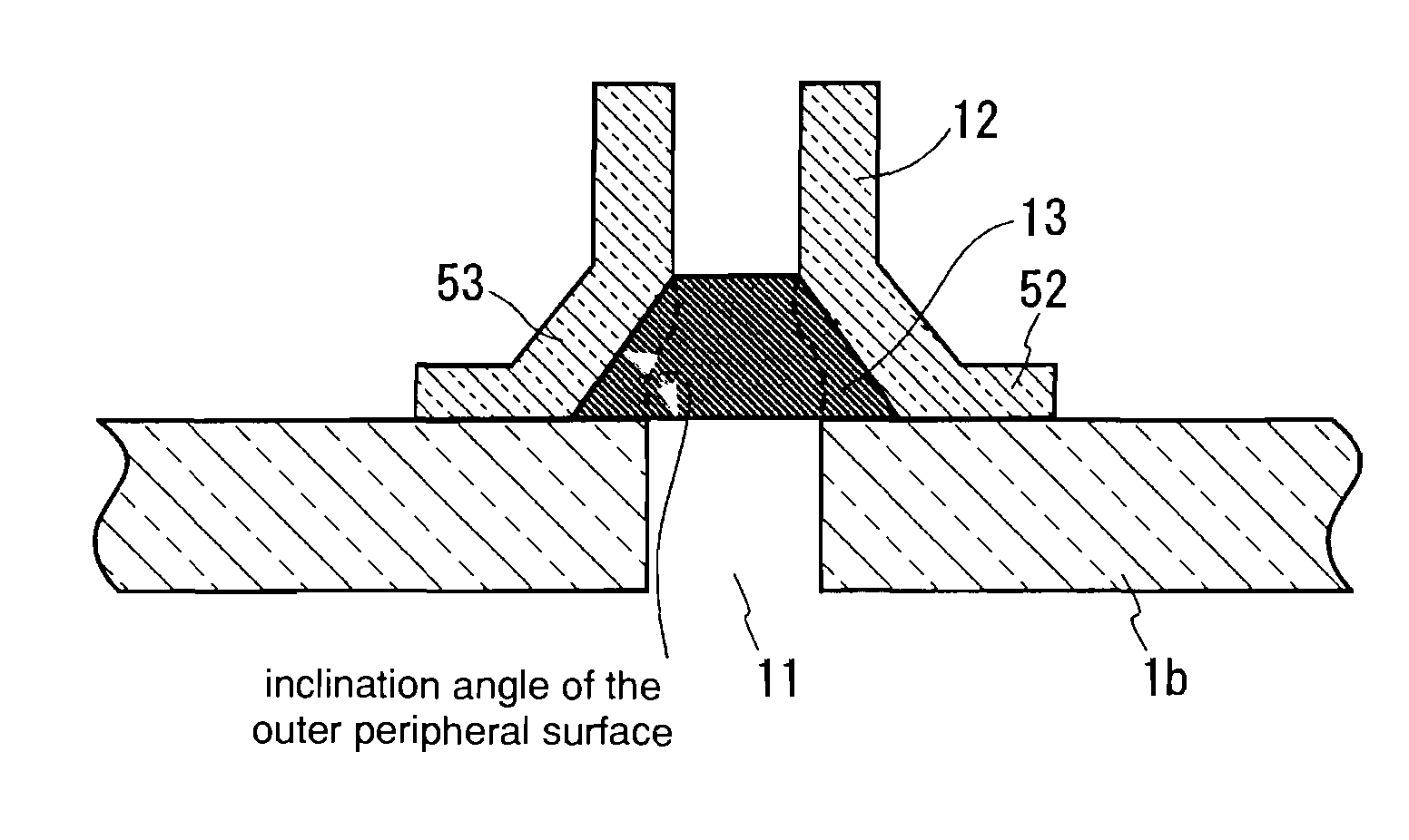
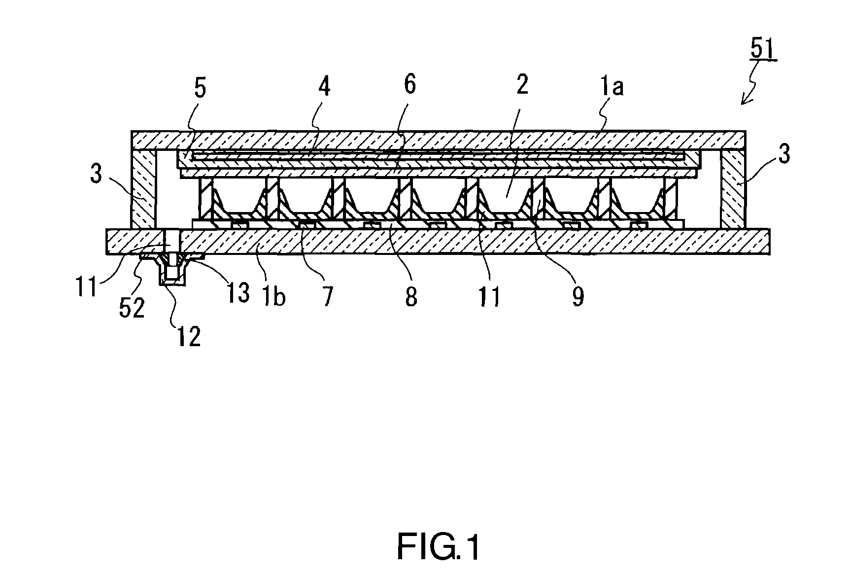
The present invention reduces the amount of lead used in a display device and improves its long-term moisture resistance. This display device includes: a panel (1b) provided with a hole (11) formed therein; a phosphate glass member (13); and a tube (12) mounted on the panel (1b) via the glass member (13) so as to cover the hole (11). The glass member (13) is bonded to at least a partial area of the inner wall surface of the tube (12) and to a partial area of the panel (1b), so that the entire periphery of the end face of the tube (12) located on the side of the hole (13) is in contact with the panel (1b).

Description

[0001]This application is a continuation of application Ser. No. U.S. 12 / 092,768, filed May 6, 2008, which is a U.S. National Stage of PCT / JP2006 / 322473, filed Nov. 10, 2006, which application is incorporated herein by reference.TECHNICAL FIELD[0002]The present invention relates to a display device such as a plasma display panel and a field emission display, and more particularly to a display device having excellent gas-tightness for a luminescence excitation space. The present invention also relates to a vent tube with a glass ring and a phosphate glass ring that are suitable for producing such a display device.BACKGROUND ART[0003]Display devices, such as a plasma display panel (hereinafter referred to as a “PDP”) and a field emission display (hereinafter referred to as an “FED”), have been gaining attention as flat panel display devices that can achieve both an increase in screen size and reductions in thickness and weight.[0004]These display devices each are provided with a pair ...

Claims


Application Information

Patent Timeline
Patent Type & Authority Applications(United States)
IPC IPC(8): H01J5/00C04B35/64B32B1/08C03B19/06C03C8/08H01J9/26H01J9/385H01J9/40H01J11/46H01J11/48H01J11/54H01J29/86
CPCC03B19/06C03C8/04C03C8/08C03C8/14C03C8/16Y10T428/1317H01J9/261H01J11/12H01J11/48H01J11/54H01J7/22H01J9/385H01J9/26
Inventor KAI, YOSHIAKIHASEGAWA, SHINYA
Owner PANASONIC CORP
Why Eureka
Try Eureka