High voltage pulse type transformer with increased coupling coefficient through primary and secondary winding proximity

a pulse type transformer and coupling coefficient technology, applied in the direction of transformer/inductance details, coils, inductances, etc., can solve the problems of low output power from the secondary winding, lead-setting is a labor-intensive and expensive process, and the number of wire ends that need to be lead-set goes up with the number of windings, so as to reduce separation and increase the coupling coefficient of the transformer

Inactive Publication Date: 2009-10-22
WOLFGRAM INDS
View PDF2 Cites 26 Cited by
  • Summary
  • Abstract
  • Description
  • Claims
  • Application Information

AI Technical Summary

Benefits of technology

[0012]The present invention provides a high voltage, high current, DC pulse type transformer for use in a high current pulse type circuit such as a capacitive discharge circuit where the core is pushed beyond saturation, with a transformer construction that increases the transformer's coupling coefficient through close proximity of the primary winding turns to the secondary winding turns. The transformer construction includes a primary winding wound around a bobbin with the secondary winding provided in a plurality of winding bays wound around the primary winding. The winding bays are provided by a frame with flanges to separate each of the winding bays while the close proximity of primary winding turns to the secondary winding t

Problems solved by technology

Pushing the transformer's core beyond saturation in DC pulse type applications such as DC to DC converters is not common because it causes the transformer to become inefficient and results in over-heating.
The smaller size and the high currents associated with capacitive discharge type circuits cause the high current DC pulse type transformer's magnetic core to become saturated such that very little increase in output power from the secondary winding is delivered for an increase in input power to the primary winding due to the transformer's magnetic coupling through the transformers magnetic core.
This lead-setting is a labor intensive and expensive process for one primary winding and one secondary winding where both ends of both windings are lead-set.
However, the number of wire ends that need to be lead-set goes up with the number of windings along with the cost.
This cumulative number of insulation layers between the secondary winding layers that are farthest away from the primary winding results in an average distance between the primary winding turns and secondary winding turns that significantly limits the coupling coefficient of the transformer when the transformer is used in a high current pulse type application where the transformer's core is pushed beyond saturation and where the coupling coefficient becomes more and more dependent on the primary and secondary winding's proximity to each other.
However, th

Method used


Image

  • High voltage pulse type transformer with increased coupling coefficient through primary and secondary winding proximity
  • High voltage pulse type transformer with increased coupling coefficient through primary and secondary winding proximity
  • High voltage pulse type transformer with increased coupling coefficient through primary and secondary winding proximity

Examples


Embodiment Construction

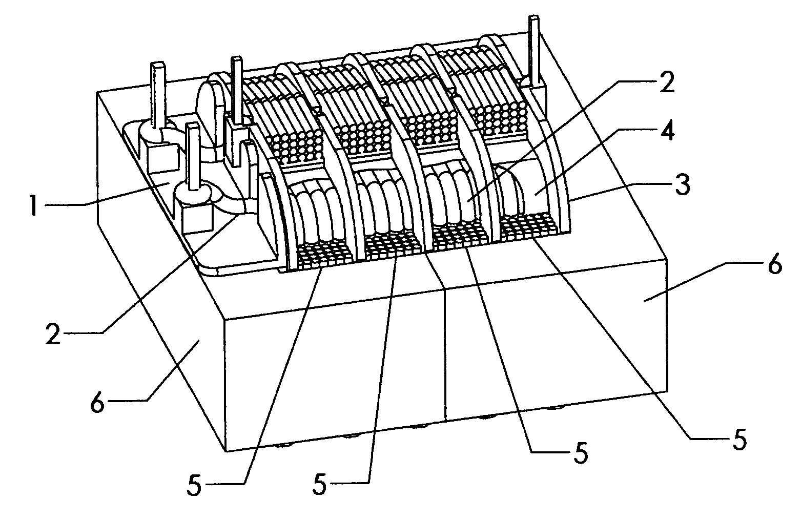
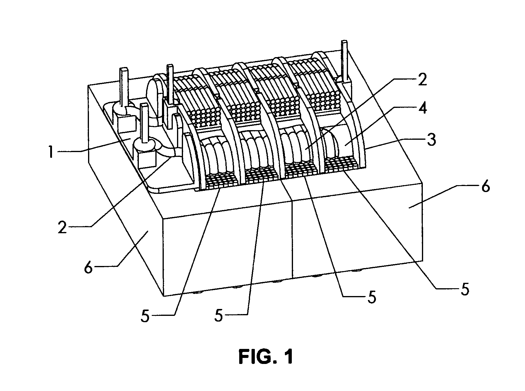
[0026]FIG. 1 is an isometric view of a preferred embodiment of the high voltage, step-up, high current DC pulse type transformer invention that increases the coupling coefficient through close proximity of the primary winding turns and secondary winding turns. In FIG. 1, a completely assembled transformer is shown with a bobbin 1, a primary winding 2, a frame 3 and separate thin insulation layer 4 combined to provide a form for winding the secondary winding 5 in close proximity to the primary winding 2. Both the primary winding 2 and secondary winding 5 are constructed using magnet wire commonly found in the transformer industry. The secondary winding 5 has an output voltage potential that is greater than the primary winding 2 such that the transformer is considered a step-up type transformer and the secondary winding 5 is a high voltage winding of sufficient output voltage potential to cause breakdown in the coating on the magnet wire used for the secondary winding 5 if the seconda...


PUM


Abstract

The present invention provides a high voltage, step-up, high current DC pulse type transformer with increased coupling coefficient between the primary and secondary windings through close proximity of the primary winding turns and secondary winding turns by means of transformer construction that provides a plurality of winding bays for a high voltage secondary winding physically located in close proximity to the primary winding. The plurality of winding bays for the secondary winding are provided by means of a frame and separate thin insulation layer where the thin insulation layer provides the barrel for all or part of the secondary winding. The invention significantly increases the transformer's coupling coefficient in high voltage step-up transformer applications where the transformer's core is pushed beyond saturation due to the high peak current typically found in capacitive discharge type circuits such as those used in electric fence controllers, strobe circuits, and high performance ignition systems for automobile, marine, or motorcycle engines.

Description

FIELD OF INVENTION[0001]The present invention relates to a high voltage, step-up, high current DC pulse type transformer for use in a high current pulse type application such as a capacitive discharge type circuit where the core is pushed beyond saturation and where the coupling coefficient becomes significantly dependent on the primary winding's physical proximity to the secondary winding, and in particular, a transformer construction that includes a frame for providing a plurality of winding bays for a high voltage secondary winding physically located in close proximity to the primary winding by means of a separate thin insulation layer that provides a barrel to wind the secondary winding.BACKGROUND OF THE INVENTION[0002]Transformers are electrical devices commonly used to transform power from an AC source to an AC load. They may also be used to electrically isolate the supply from the load by providing adequate insulation and creepage distance between the primary and secondary wi...

Claims


Application Information

Patent Timeline
IPC IPC(8): H01F27/28
CPCH01F27/325H01F27/326H01F2038/026H01F38/10H01F2005/022H01F38/02
Inventor WOLFGRAM, KIRK W.
Owner WOLFGRAM INDS
Why Eureka
Try Eureka