An imaging system with two imaging modalities

a technology of imaging system and imaging modalities, applied in the field of imaging system, can solve the problems of inability to characterize in-vivo plaque on a cellular/molecular level, inability to properly perform detailed plaque inspection with current techniques, and inability to achieve accurate and accurate detection results. , the effect of miniaturisation and efficient control of the optical lens system

Inactive Publication Date: 2009-10-22
KONINKLIJKE PHILIPS ELECTRONICS NV
View PDF7 Cites 43 Cited by
  • Summary
  • Abstract
  • Description
  • Claims
  • Application Information

AI Technical Summary

Benefits of technology

[0018]Beneficially, the catheter may comprise first control means arranged for changing the numerical aperture of the optical lens system between the first numerical aperture (1NA) and the second numerical aperture (2NA), e.g. dedicated conductors within the catheter may supply power and control the adjustable part of the lens system. Similarly, the imaging unit may comprise second control means arranged for changing between imaging with the first (1IM) and the second (2IM) imaging modalities of the imaging unit, and the first and second control means then further being arranged for mutual interaction, e.g. synchronisation, with respect to change of imaging i.e. changing of imaging mode. This can provide a reliable coordination between the catheter and the image unit.
[0019]In one embodiment, the changeable numerical aperture between the first numerical aperture (1NA) and the second numerical aperture (2NA) is provided by an active optical component. An active optical component can be defined as an optical component having optical parameters changeable upon external influence on the component, e.g. by electrical or acoustical means etc., but not a movement of the optical component. This further enables miniaturisation and efficient control of the optical lens system. The optical lens system may for example comprise a liquid lens so as to provide a numerical aperture which is changeable between the first numerical aperture (1NA) and the second numerical aperture (2NA), the liquid lens facilitating both gradual changes in the numerical aperture or fast and / or abrupt changes in the numerical aperture. Alternatively, the optical lens system may comprise a liquid crystal (LC) lens so as to provide a numerical aperture which is changeable between the first numerical aperture (1NA) and the second numerical aperture (2NA).
[0020]In another embodiment, the optical lens system may comprise a set of lenses being relatively displaceable along an optical axis of the optical lens system so as to provide a numerical aperture which is changeable between the first numerical aperture (1NA) and the second numerical aperture (2NA). Thus, the set of lenses can be moved in relation to each other to provide a changeable numerical aperture. This offers a quite simple design though the dynamic range of numerical apertures available may be lower as compared to an active optical component when considering the available space within the catheter.

Problems solved by technology

This detailed plaque inspection cannot be performed properly with current techniques like conventional angiography, magnetic resonance angiography (MRA) or computed tomographic angiography (CTA).
Although various modalities exist to characterize plaque, methods to get detailed information in vivo on the cellular and molecular level of plaque are still underdeveloped.
), but they are not able to characterize in-vivo the plaque on a cellular / molecular level.
However the lens geometry is fixed making such devices quite inflexible with respect to change of imaging depth and / or imaging technique.
Furthermore, OCT only provides only limited molecular information of tissue.

Method used


Image

  • An imaging system with two imaging modalities
  • An imaging system with two imaging modalities
  • An imaging system with two imaging modalities

Examples


Embodiment Construction

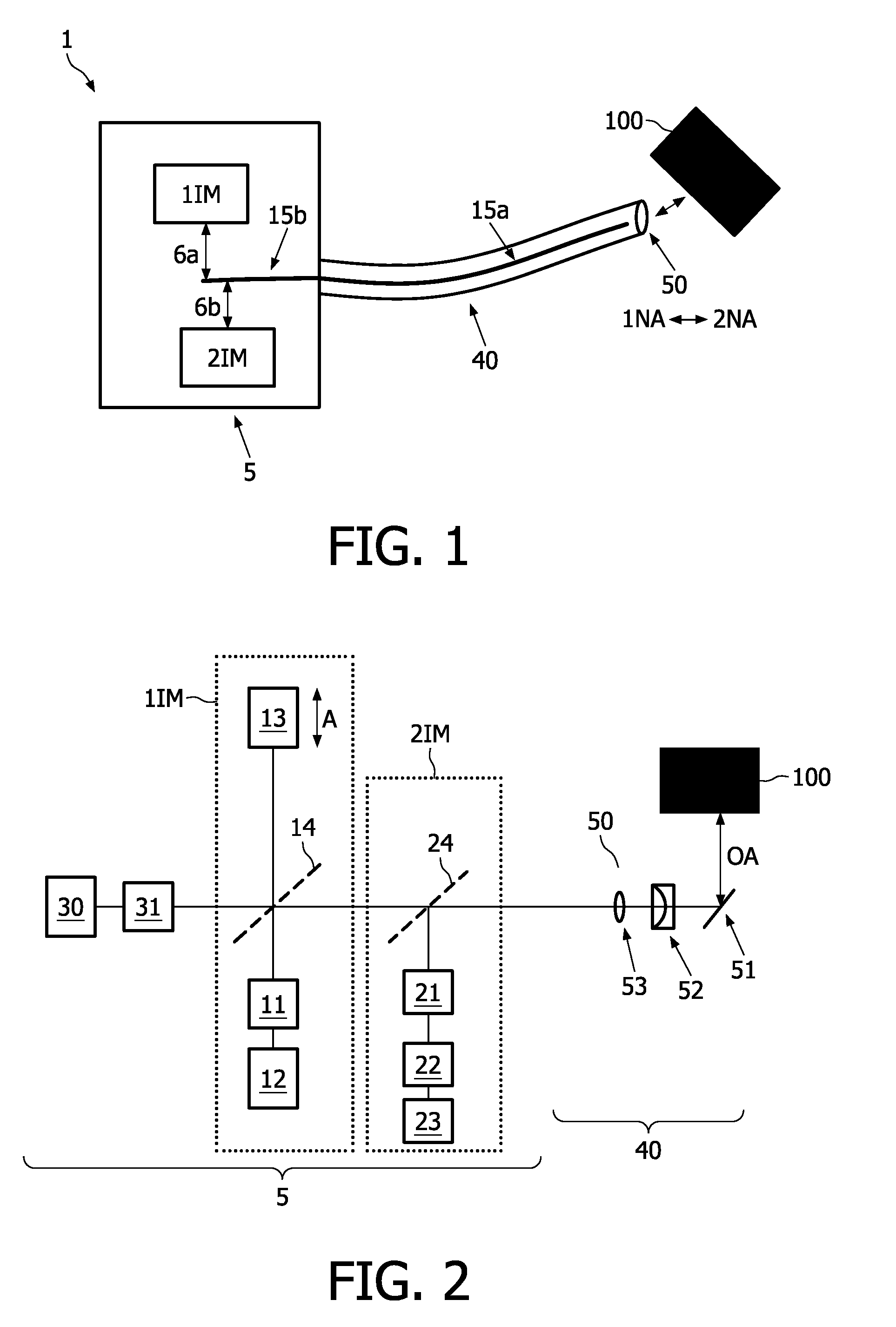
[0045]FIG. 1 is a schematic drawing of the imaging system 1 according to the present invention. The imaging system 1 comprises two main parts, i.e. a catheter 40 and an imaging unit 5. The catheter 40 and the imaging unit 5 can be disconnected. Typically, the catheter 40 is disposable after one-time use, but the catheter 40 can also be reusable if the catheter 40 is suited for sufficiently hygienic cleaning.

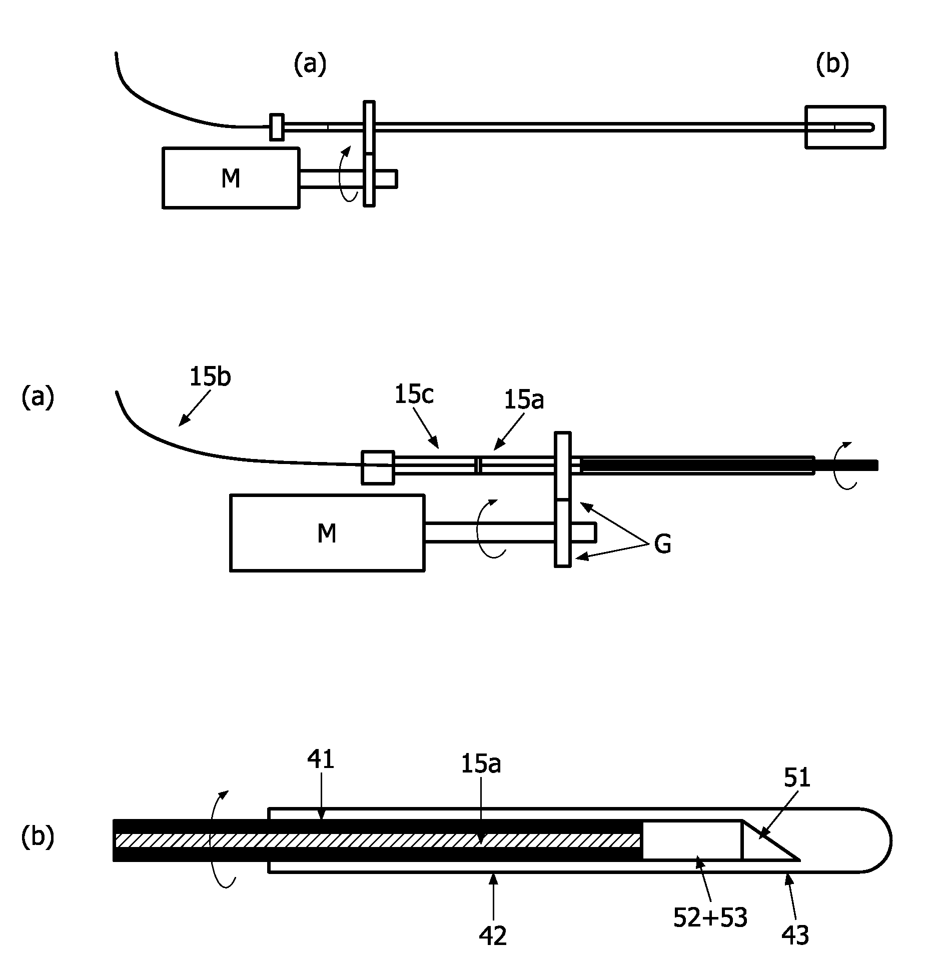
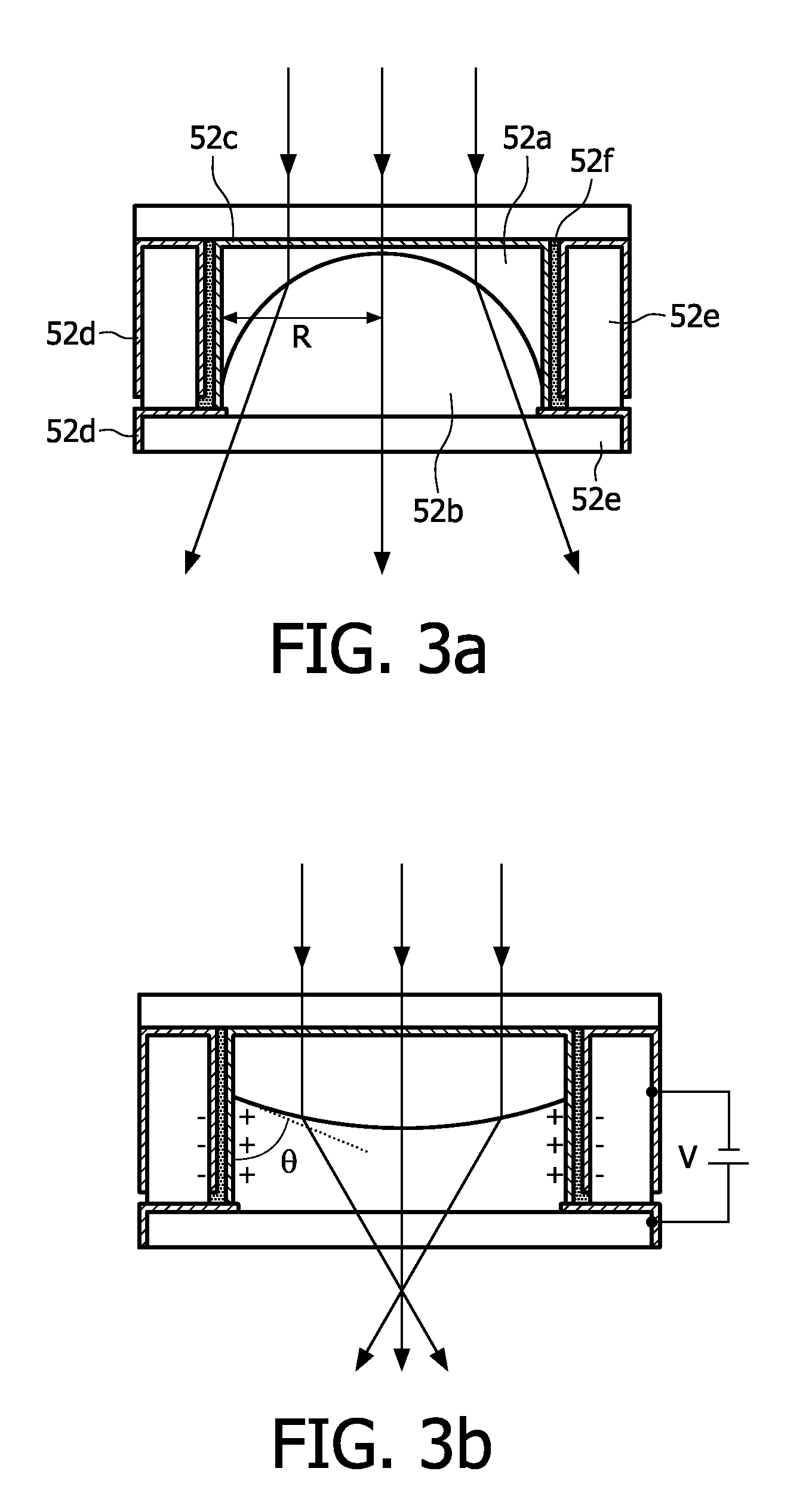
[0046]The catheter has an optical lens system 50, which is situated at an end portion of the catheter 40. The lens system 50 is optically connected to optical guide means 15a for guiding light through the catheter 40. The optical lens system 50 has a numerical aperture NA, which is changeable between a first numerical aperture 1NA and a second numerical aperture 2NA as indicated in the Figure. The second numerical aperture 2NA is higher than the first numerical aperture 1NA: 2NA>1NA.

[0047]The imaging unit 5 is arranged for optical imaging in co-operation with the catheter 40. The...


PUM


Abstract

The invention relates to an imaging system 1 with two modalities, the system has a catheter 40 with an optical lens system 50 situated at an end of the catheter and optically connected to optical guide means 15a. The lens system has a numerical aperture which is changeable between a first 1NA and second 2NA numerical aperture, 2NA being larger than 1NA. The imaging system also has an imaging unit 5 being arranged for optical imaging with the catheter 40. A first imaging modality 1IM and a second imaging modality 21IM are optically connectable with the optical lens system 50 of the catheter 40. The imaging system can change between imaging in two modes: (1) the first numerical aperture 1NA of the optical lens system 50 and the first imaging modality 1IM of the imaging unit 5, and (2) the second numerical aperture 2NA of the optical lens system 50 and the second imaging modality 2IM of the imaging unit 5. The invention can provide fast and flexible in-vivo imaging because the change between the first and the second imaging modality can be performed quite fast, and accordingly the first and second imaging modality can be chosen to complement each other.

Description

FIELD OF THE INVENTION[0001]The present invention relates to an imaging system with two or more imaging modalities, a corresponding catheter, a corresponding imaging unit, and a corresponding method.BACKGROUND OF THE INVENTION[0002]Interventional imaging of patients is an area of promising progress. Catheter-based treatments in the cardiovascular field, such as stent placing and aneurism treatment, are exceeding several million interventions per year. The benefits of these minimal invasive techniques compared to open surgery are numerous. To further reduce the risks for the patients during interventions and to open up new catheter-based treatments, the local diagnosis of the diseased cardiovascular tissue must be further improved.[0003]Arteriosclerosis (plaque) forms an important disease affecting millions of people. Among the various types of plaque, the vulnerable plaque (sometimes call high-risk plaque) is the life threatening form, which is responsible for about 70% of fatal acu...

Claims


Application Information

Patent Timeline
Patent Type & Authority Applications(United States)
IPC IPC(8): A61B1/06
CPCA61B5/0059A61B5/0068A61B2562/0242G02B23/26G02B21/0028G02B23/243G02B3/14A61B5/0035
Inventor HENDRIKS, BERNARDUS HENDRUKUS WILHELMTHOOFT, GERTKUIPER, STEIN
Owner KONINKLIJKE PHILIPS ELECTRONICS NV
Why Eureka
Try Eureka