Static phase shedding for voltage regulators based upon circuit identifiers

a voltage regulator and circuit identifier technology, applied in the direction of electric variable regulation, process and machine control, instruments, etc., can solve the problems of ineffective solutions, cpu usually has maximum power consumption, and prior methods that have not been successfully implemented in cpu vr

Active Publication Date: 2009-10-29
DELL PROD LP
View PDF12 Cites 24 Cited by
  • Summary
  • Abstract
  • Description
  • Claims
  • Application Information

AI Technical Summary

Benefits of technology

[0009]Systems and methods disclosed herein provide static phase shedding techniques that improve the efficiency of multiphase voltage regulators within information handling systems by selecting the number of active phases for the multiphase voltage regulators using circuit identifiers (IDs) for circuitry configured to be powered by the multiphase voltage regulators, such as central processing units (CPUs). Static phase shedding allows for selection of the number of phases for a multi-phase voltage regulator that will be active and usable by the system during its operation. The number of phases selected can be from one to the total number of phases within the multi-phase voltage regulator based upon the circuit identification information. For example, processor identifier information for CPUs can be determined during system start-up and / or initialization and then can be used to control the voltage regulator (VR) phase number to provide static phase shedding. This VR control can be implemented, for example, with conventional analog multiphase VR controllers and / or digital VR controllers, as desired. Dynamic phase shedding can also be used in conjunction with this static phase shedding to further reduce the number of active phases when a processor operates in a low power mode. In other embodiments, the static phase shedding techniques described herein can be used for a VR for memory circuitry. For example, the phase number of such a memory VR can be re-configured after memory configuration is identified after the system completes start up initialization. As described below, other features and variations can be implemented, if desired, and related systems and methods can be utilized as well.

Problems solved by technology

Typically, voltage regulators are designed to support the highest performance CPU that may be installed in the system, and such CPU usually has maximum power consumption.
These prior methods have not been successfully implemented in a CPU VR because there is not enough time for the VR to respond adequately to CPU transient operation.
One disadvantage with these prior voltage regulator solutions is that they lead to inefficient solutions where a user upgrades or downgrades to a different processor and / or where a manufacturer installs processors with different power needs into the same system motherboard.
Voltage regulators designed to handle efficiently high power needs of possible high performance microprocessors that could be installed in such systems suffer from poor power efficiency at lighter loads.
As such, when a lower performance microprocessor is installed in the same system, the voltage regulator efficiency suffers.

Method used


Image

  • Static phase shedding for voltage regulators based upon circuit identifiers
  • Static phase shedding for voltage regulators based upon circuit identifiers
  • Static phase shedding for voltage regulators based upon circuit identifiers

Examples


embodiment 100

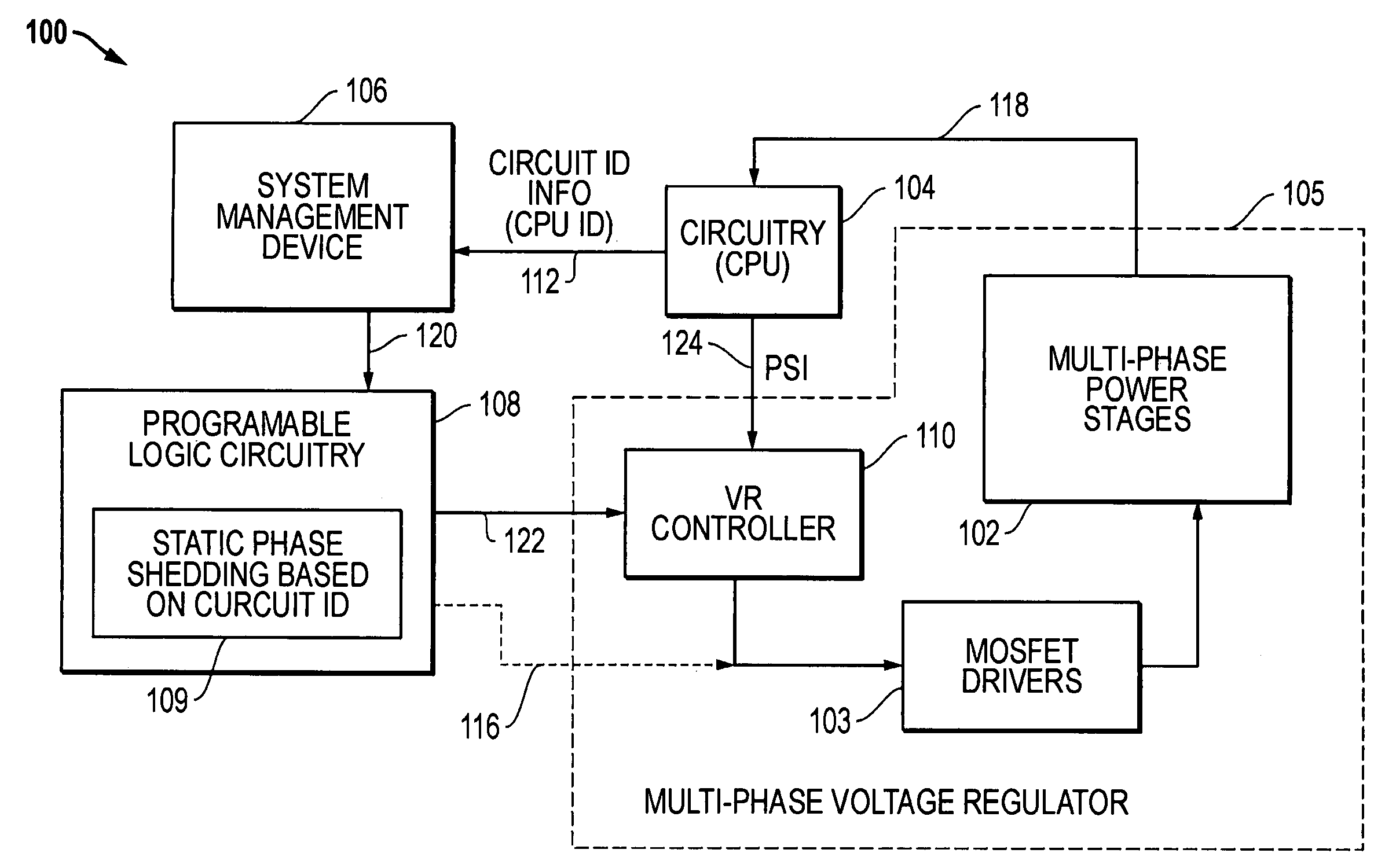
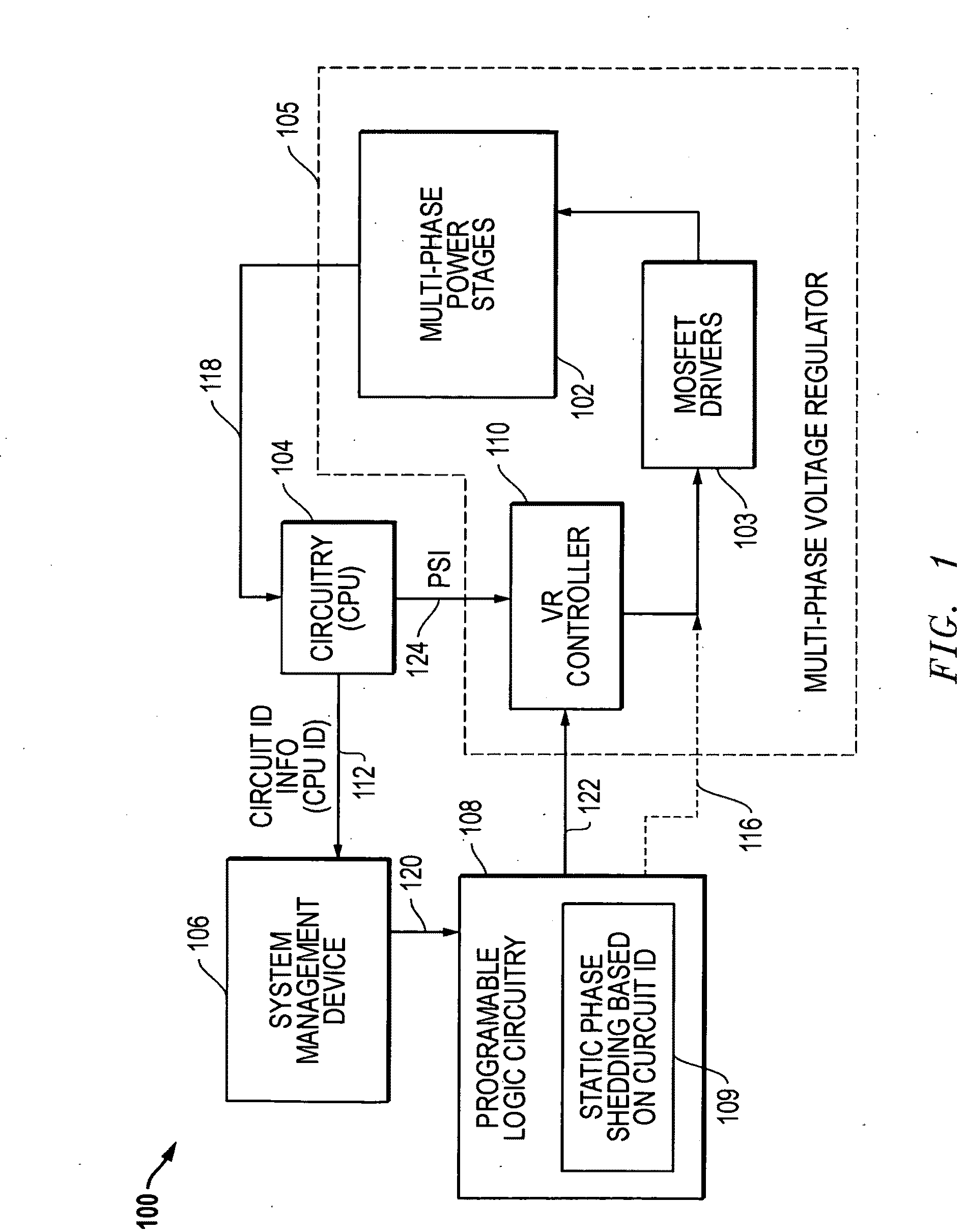
[0022]FIG. 1 is a block diagram of an embodiment 100 for a static phase shedding system for controlling a multiphase voltage regulator. As depicted, a multi-phase VR 105 provides regulated voltages to circuitry 104, such as a central processing unit (CPU) through VR lines 118. The circuitry / CPU 104 is coupled to a system management device (SMD) 106, such as board management controller (BMC), and provides circuitry identifier (ID) information 112, such as a CPU ID, to the SMD 106. The SMD 106 is coupled to provide control signals 120 to programmable logic circuitry (PLC) 108, such as a CPLD (complex programmable logic device), configured to provide desired phase control. For example, a static phase shedding control module 109 can be provided within the PLC 108 to provide static phase shedding based upon circuit ID information 112, such as a CPU ID. The PLC 108 in turn sends phase control signals 122 to the VR controller 110. The VR controller 110 in turn provides phase control signal...

embodiment 200

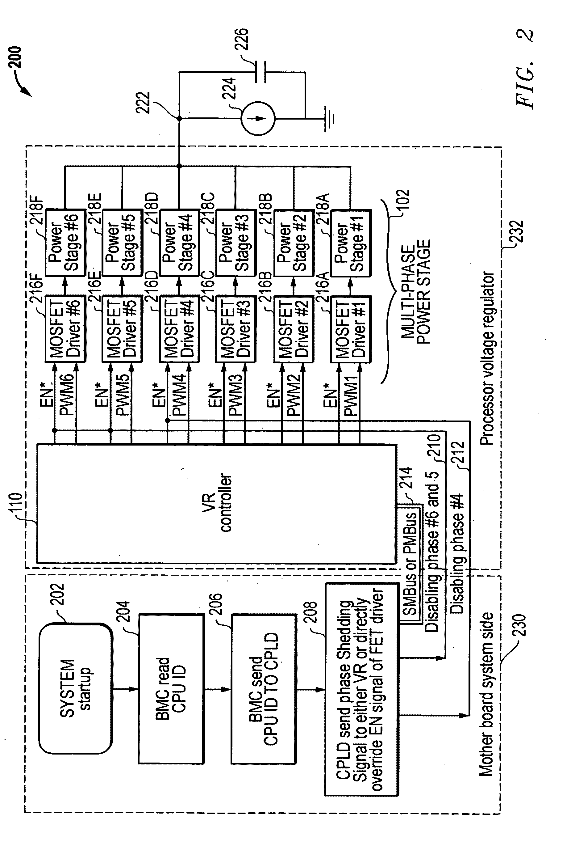
[0024]FIG. 2 is a more detailed block diagram for an example static phase shedding embodiment 200 using a BMC as the SMD 106 and a CPLD as the PLC 108. As depicted, the embodiment 200 includes mother board system side processes 230 and a processor voltage regulator (VR) 232. The mother board system side processes 230 describe processes that occur in the initialization and selection of the number of active phases for the processor VR 232. The processor VR 232 produces a regulated voltage output 222 that drives a processor load represented by current source 224 and capacitor 226.

[0025]Looking to the mother board system side processes 230, block 202 represents the startup of the system. In block 204, a BMC or BIOS (as discussed below) reads and / or receives the CPU ID for the CPU installed in the system. In block 206, the BMC sends the CPU ID to a controller, such as a CPLD, configured to control on board system operations. In block 208, the CPLD sends phase shedding control signals to ...

embodiment 300

[0032]FIG. 3 is process flow diagram of an embodiment 300 for static phase shedding control of a multi-phase voltage regulator where three levels of processors are expected to be installed. Block 302 represents the start-up of the system. In block 304, all VR phases are enabled for maximum power rating capability. In block 305, the CPU ID information is determined and reported to the phase control circuitry. As indicated above, this control circuitry could be implemented using a variety techniques, including the use of a BMC or system BIOS to read the CPU ID from a specific register and then to send the CPU ID information to a programmed CPLD. In decision block 306, a determination is made concerning the desired number of active phases for the VR based upon the power level requirements indicated by the CPU ID. Block 308 is then selected if a 3-phase configuration is desired, for example, where the processor identifier information indicates lower level power requirements. Block 310 i...


PUM


Abstract

Systems and methods are disclosed that provide static phase shedding techniques to improve the efficiency of multi-phase voltage regulators within information handling systems by selecting the number of active phases for the multi-phase voltage regulators using circuit identifiers (IDs) for circuitry configured to be powered by the multi-phase voltage regulators, such as central processing units (CPUs). In one embodiment, processor identifier information related to installed CPUs is used to control the voltage regulator (VR) phase number to provide static phase shedding. This VR control can be implemented in a variety of ways, including the use of conventional analog multi-phase VR controllers and / or digital VR controllers. Dynamic phase shedding can also be used in conjunction with this static phase shedding to further reduce the number of active phases when a processor operates in a low power mode.

Description

TECHNICAL FIELD [0001]The techniques described herein relate to voltage regulators for circuitry such as central processing units (CPUs) on computer motherboards and, more particularly, to the controlling the regulated voltage provided by voltage regulators to such circuitry.BACKGROUND [0002]As the value and use of information continues to increase, individuals and businesses seek additional ways to process and store information. One option available to users is information handling systems. An information handling system generally processes, compiles, stores, and / or communicates information or data for business, personal, or other purposes thereby allowing users to take advantage of the value of the information. Because technology and information handling needs and requirements vary between different users or applications, information handling systems may also vary regarding what information is handled, how the information is handled, how much information is processed, stored, or c...

Claims


Application Information

Patent Timeline
IPC IPC(8): G05F1/00
CPCH02J1/102
Inventor LUO, SHIGUOBREEN, JOHN J.ZHAO, HONGTAO
Owner DELL PROD LP
Why Eureka
Try Eureka