Swashplateless helicopter blade actuation system

a blade actuation system and blade technology, applied in the field of blade actuation systems, can solve the problems of fatigue damage to structural components of the helicopter, excessive vibration and noise, and reduce passenger and crew comfort, so as to eliminate or reduce maintenance costs, simplify the design, and facilitate the provision of power.

Active Publication Date: 2009-10-29
THE BOEING CO
View PDF7 Cites 40 Cited by
  • Summary
  • Abstract
  • Description
  • Claims
  • Application Information

AI Technical Summary

Benefits of technology

[0023]By co-locating the generators with the rotor head, power may be easily provided to the motors while avoiding the use of slip rings for power transfer. The motors and generators may be configured as electromechanical devices to simplify the design and eliminate or reduce maintenance costs normally associated with hydraulic systems that are typically implemented in conventional helicopter rotor control systems.
[0024]The motors ...

Problems solved by technology

One of the primary problems associated with helicopter flight is excessive amounts of vibration and noise generated by rotation of the main rotor blades.
Rotor-induced vibration may occur as a result of rotor-induced shear forces and moments acting at the rotor hub and can reduce passenger and crew comfort and cause fatigue damage to structural components of the helicopter.
Rotor-induced noise can also reduce passenger and crew comfort and is frequently the source of complaints from individuals due to helicopter overflights.
Flight performance and efficiency can be limited by the ability to control the pitch angle of the rotor blades.
For example, forward speed of the helicopter may be limited by inefficiencies associated with non-optimal pitch angles of the rotor blades at any given point during the revolution of each rotor blade.
Unfortunately, due to geometry and configuration constraints of conventional swashplate designs, only certain frequencies (i.e., the nth harmonic of an n-bladed r...

Method used


Image

  • Swashplateless helicopter blade actuation system
  • Swashplateless helicopter blade actuation system
  • Swashplateless helicopter blade actuation system

Examples


Embodiment Construction

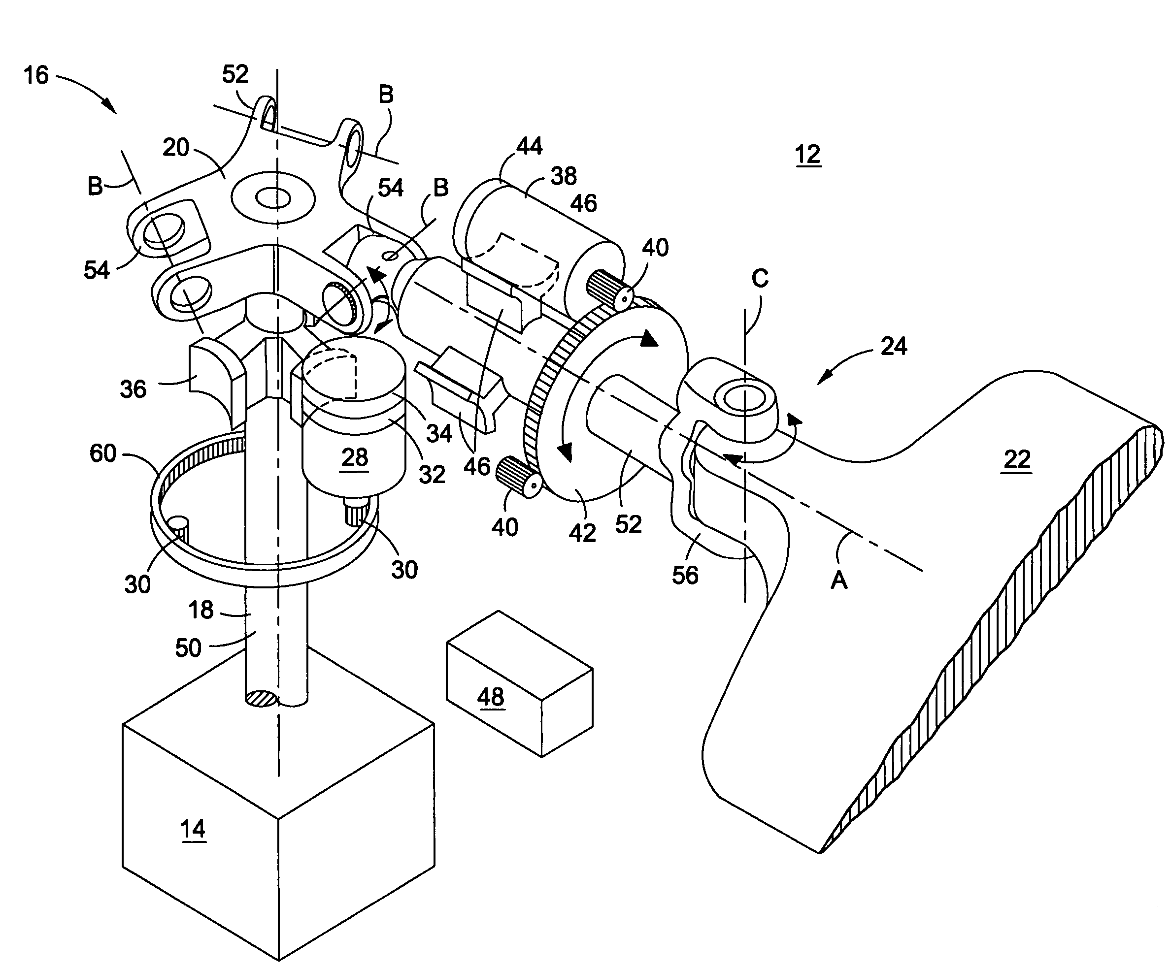
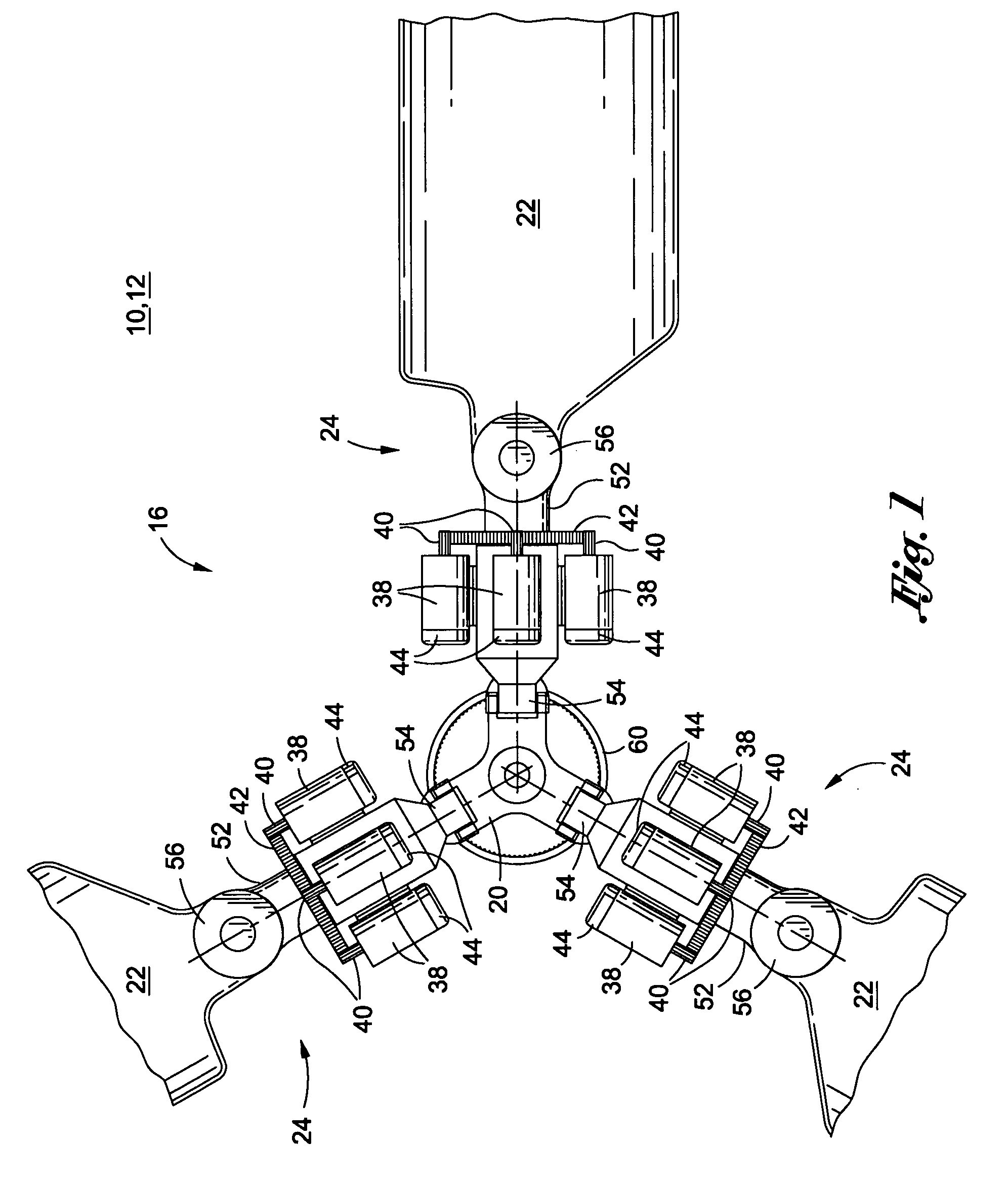
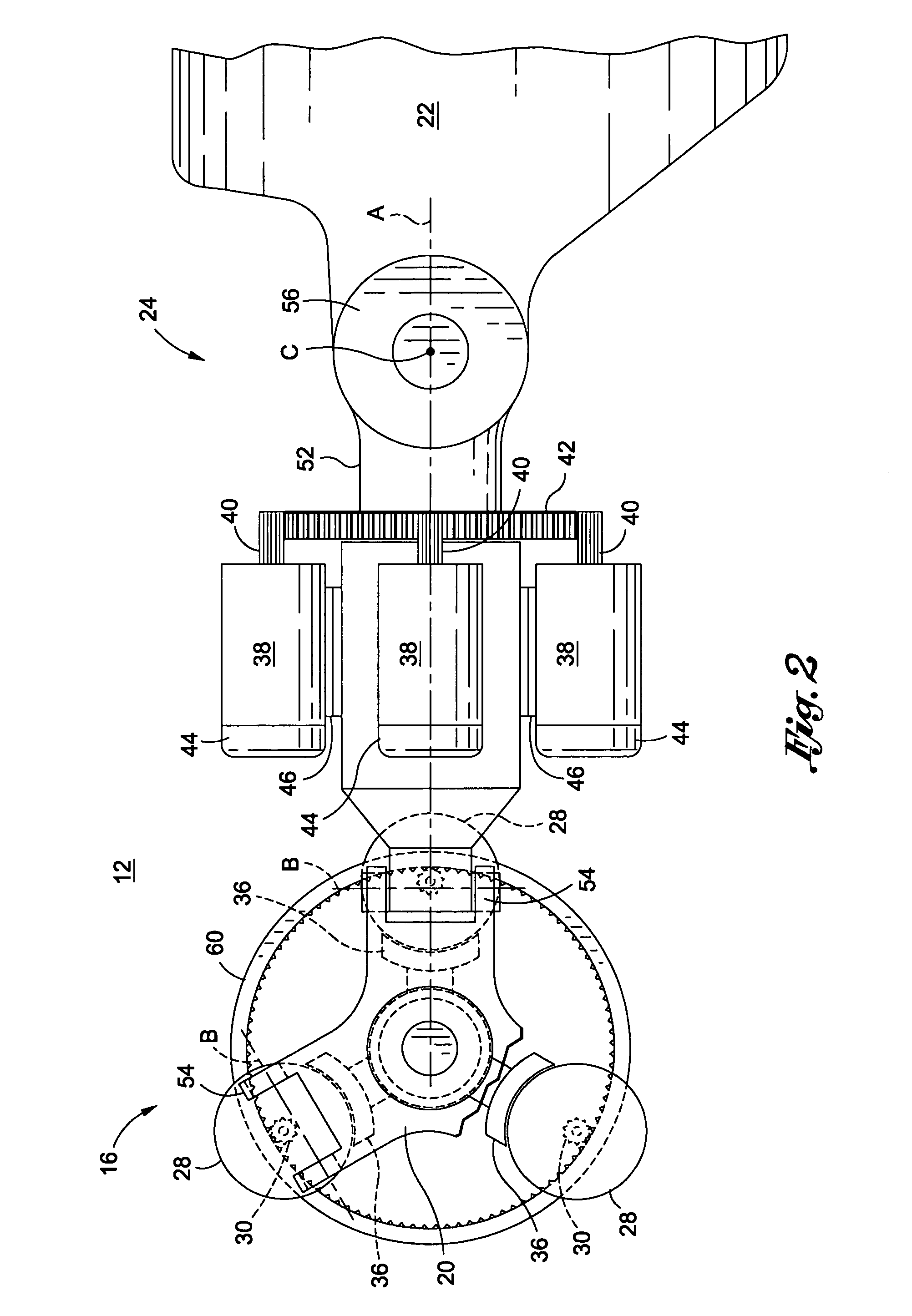
[0035]Referring now to the drawings wherein the showings are for purposes of illustrating preferred and various embodiments of the present disclosure only and not for purposes of limiting the same, FIGS. 1-4 illustrate a blade actuation system 12 as may be implemented on a helicopter 10 or other rotorcraft. The rotorcraft or helicopter 10 may comprise a rotor drive mechanism 14 such as an engine and / or transmission as part of a non-rotating frame 64 of the helicopter 10. As part of the rotating frame 62, a rotatable rotor shaft 18 may extend outwardly from the drive mechanism. A rotor hub 20 may be fixedly connected to a rotor head 16 mounted on the rotor shaft 18. A plurality of rotor blades 22 may be connectable to the rotor hub 20.

[0036]In one embodiment, the blade actuation system 12 comprises at least one and, more preferably, a plurality of motors 38 which may be operatively coupled to at least one of the rotor blades 22. The motors 38 may be provided in sets of three in order...


PUM


Abstract

A blade actuation system comprises at least one motor coupled to a rotor blade for changing the pitch angle of the rotor blade. The motor is configured to wirelessly communicate with at least one flight control computer to modulate the pitch angle. At least one generator may be mounted on a rotor shaft to generate power during rotation of the rotor shaft. The generator may provide power to the motor. The flight control computer is operative to provide control signals to at least one of the generators and motors for regulation thereof. The flight control computer, motor and generator may be configured to wirelessly communicate with one another.

Description

CROSS-REFERENCE TO RELATED APPLICATIONS[0001]This invention was made with Government support under Agreement No. W911W6-06-2-0002 for the National Rotorcraft Technology Center Research Program. The Government has certain rights in the invention.STATEMENT RE: FEDERALLY SPONSORED RESEARCH / DEVELOPMENT[0002](Not Applicable)FIELD[0003]The following disclosure relates generally to rotorcraft and, more particularly, to a blade actuation system and method for individually controlling the rotor blades of a helicopter.BACKGROUND[0004]Helicopters include one or more main rotors each having a plurality of rotor blades. The rotor blades are rotatably driven by a drive mechanism such as an engine via a transmission. Helicopter flight is regulated by cyclic and collective control of the angle of incidence or pitch angle of the rotor blades.[0005]In collective control, the pitch angle of the rotor blades is collectively changed all at once such that the amount of lift produced by the rotor blades i...

Claims


Application Information

Patent Timeline
IPC IPC(8): B64C27/605
CPCB64C27/72Y02T50/34B64C2027/7216Y02T50/30
Inventor RUDLEY, FRANK M.MYCHALOWYCZ, EVHEN M.WAGNER, JR., JOSEPH R.GLEMBOCKI, EDWARD J.
Owner THE BOEING CO
Why Eureka
Try Eureka