Method and apparatus for cleaning of a CVD reactor

a technology of cvd reactor and process chamber, which is applied in the direction of vacuum evaporation coating, cleaning using liquids, coatings, etc., can solve the problems of changing the surface characteristics of the process chamber, affecting the cleaning effect of the reactor, so as to achieve efficient and uniform plasma cleaning, and high utilization efficiency of reactive species

Inactive Publication Date: 2009-10-29
ASM JAPAN
View PDF0 Cites 365 Cited by
  • Summary
  • Abstract
  • Description
  • Claims
  • Application Information

AI Technical Summary

Benefits of technology

[0005]An object of the present invention is to provide a process and an apparatus for efficient and uniform remote plasma cleaning of a process chamber of a chemical vapor deposition (CVD) reactor.
[0006]Another object of the present invention is to provide a process and an apparatus that enables high utilization efficiency of the reactive species.
[0007]Yet another object of the present invention is to provide a process and an apparatus that can control the flow rate of the reactive species.
[0008]To achieve the objects mentioned above, the present invention provides a process and an apparatus that includes supplying the reactive species into the process chamber of the CVD reactor through a plurality of inlet holes. The plurality of inlet holes is located on a ring-shaped first body. The reactive species are generated in a remote plasma unit and are supplied to the process chamber through a first conduit. The first conduit connects the remote plasma unit to the first body. The reactive species are introduced into the process chamber via the plurality of inlet holes. This ensures the high utilization efficiency of the reactive species and uniform cleaning of the process chamber. Further, the flow rate of the reactive species can be controlled by inserting one or more parts into one or more of the plurality of inlet holes of the first body or by changing the flow rate of a cleaning gas. The reactive species react with unwanted deposited films in the process chamber and produce volatile products that are then exhausted from the process chamber.

Problems solved by technology

During the deposition process, unwanted films and particulate materials accumulate on surfaces other than the target substrate.
These unwanted films and particulate materials can change the surface characteristics of the process chamber.
Further, the unwanted films and particulate materials can flake off from the walls of the process chamber and get deposited on the wafers, causing defects on their surfaces.
Therefore, a substantial portion of the reactive species is wasted, resulting in low utilization and cleaning efficiency and non-uniform cleaning.
This results in increased downtime of the reactor.

Method used


Image

  • Method and apparatus for cleaning of a CVD reactor
  • Method and apparatus for cleaning of a CVD reactor
  • Method and apparatus for cleaning of a CVD reactor

Examples


first embodiment

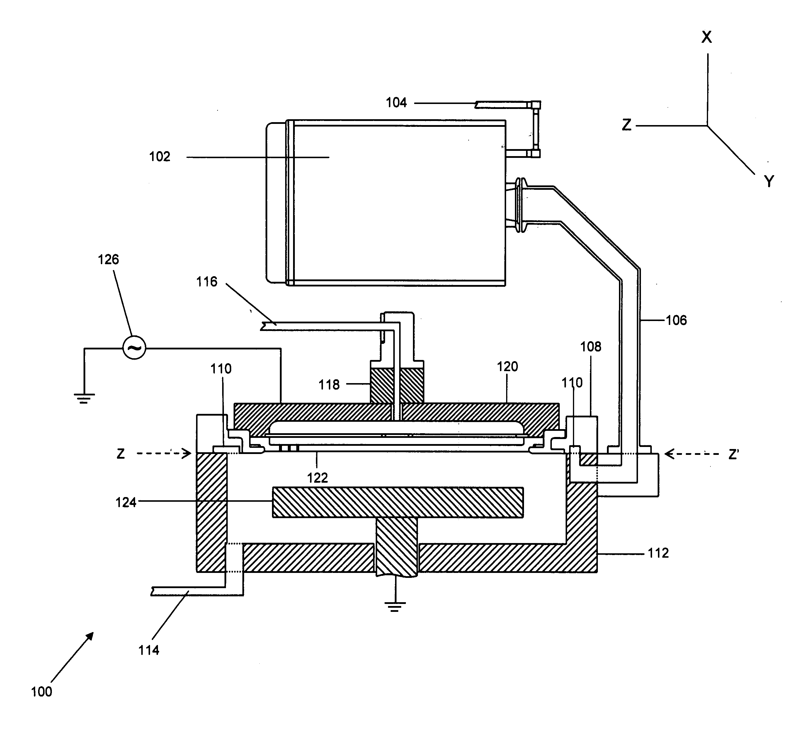
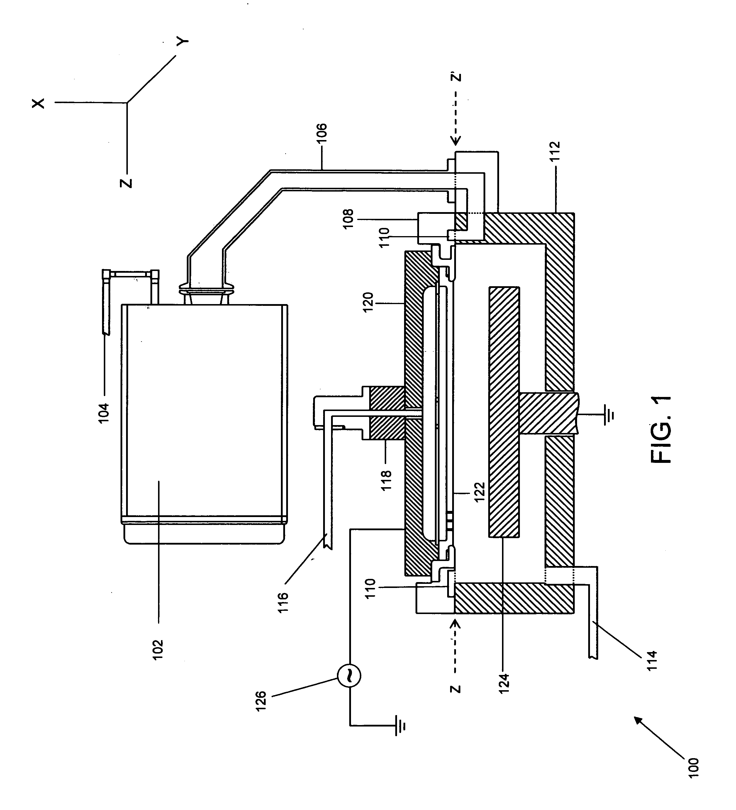
[0018]FIG. 1 is a cross-sectional view of a CVD apparatus that is coupled with a remote plasma unit, in accordance with the invention. Apparatus 100 includes remote plasma unit 102, a cleaning gas inlet 104, a first conduit 106, a first body 108, a plurality of inlet holes 110, a second body 112, an exhaust line 114, a second conduit 116, an insulator 118, an upper body 120, a shower plate 122, a susceptor 124, and a radio frequency (RF) generator 126.

[0019]The reactive species used in remote plasma cleaning are free radicals and are generated in remote plasma unit 102. In various embodiments of the present invention, the reactive species may be fluorine radicals, oxygen radicals, and the like. The reactive species are generated from a cleaning gas, which is supplied to remote plasma unit 102 through cleaning gas inlet 104. In an embodiment of the invention, the cleaning gas is a mixture of oxygen, a rare gas such as Ar, and an additive gas such as N2 gas. In an embodiment of the in...

second embodiment

[0026]FIG. 3 is a cross-sectional view of a CVD apparatus that is coupled with a remote plasma unit in accordance with the invention. FIG. 3 includes remote plasma unit 102, cleaning gas inlet 104, first conduit 106, first body 108, a tunnel 302, a plurality of inlet holes 304, second body 112, exhaust line 114, second conduit 116, insulator 118, upper body 120, shower plate 122, susceptor 124, and radio frequency (RF) generator 126.

[0027]In accordance with the second embodiment of the invention, first conduit 106 is connected to an upper part of first body 108 directly and not through second body 112. The process chamber can be cleaned in accordance with the second embodiment of the invention under the process conditions as described in the first embodiment of the invention.

[0028]FIG. 4 is a perspective view of a first body in accordance with the second embodiment of the invention. FIG. 4 includes first body 108, an inlet 402, tunnel 302 and the plurality of inlet holes 304. First ...

third embodiment

[0029]FIG. 5 is a cross-sectional view of a CVD apparatus in accordance with the invention. FIG. 5 includes second body 112, exhaust line 114, second conduit 116, shower plate 122, susceptor 124, RF generator 126, an inner pipe 502, a vertical passage 504 of the inner pipe, a first plate 506, an outer pipe 508, a vertical passage 510 of the outer pipe, a second plate 512, a third plate 514, and a plurality of inlet holes 516.

[0030]Second conduit 116 supplies the process gas to inner pipe 502. The process gas is supplied through the vertical passage 504 of inner pipe 502 to first plate 506. First plate 506 distributes the process gas uniformly to shower plate 122. Shower plate 122 supplies the process gas to the process chamber. The reactive species are supplied through outer pipe 508 and pass through the vertical passage 510 of the outer pipe 508. Second plate 512 changes the direction of the flow of the reactive species and is attached to the upper portion of first plate 506. The r...


PUM

PropertyMeasurementUnit
poweraaaaaaaaaa
pressureaaaaaaaaaa
pressureaaaaaaaaaa

Abstract

The present invention provides a process and an apparatus for remote plasma cleaning of a process chamber of a chemical vapor deposition (CVD) reactor. The reactive species are generated in a remote plasma unit and are introduced into the process chamber through a plurality of inlet holes. The reactive species are free radicals such as oxygen radicals, fluorine radicals, and the like. These reactive species react with the unwanted residues in the process chamber and generate volatile products. The invention also provides a method for controlling the flow rate of the reactive species.

Description

BACKGROUND[0001]The present invention relates to a method for cleaning a process chamber of a reactor. More specifically, the present invention relates to remote plasma cleaning of a process chamber of a chemical vapor deposition (CVD) reactor.[0002]In the semiconductor industry, selected materials are deposited on a target substrate to produce electronic components. The various deposition techniques employed in the industry include chemical vapor deposition (CVD), plasma enhanced chemical vapor deposition (PECVD), atomic layer deposition (ALD), and the like. In the CVD process, vaporized gaseous reactants are introduced into a process chamber and result in the formation of films on the target substrate. During the deposition process, unwanted films and particulate materials accumulate on surfaces other than the target substrate. The unwanted films and particulate materials may accumulate on the walls of the process chamber, susceptor, and on other employed equipment. These unwanted...

Claims


Application Information

Patent Timeline
Patent Type & Authority Applications(United States)
IPC IPC(8): C23C14/58B08B6/00C25F1/00
CPCC23C16/4405
Inventor OKURA, SEIJI
Owner ASM JAPAN
Why Eureka
Try Eureka