Lightweight, Durable Lead-Acid Batteries

a lead-acid battery, lightweight technology, applied in the manufacture of final products, cell components, coatings, etc., can solve the problems of low specific energy of lead-acid batteries, limited use of electric and hybrid-electric vehicle applications, and corrosion between the interface of lead peroxide active materials and grid materials, so as to reduce weight, improve durability, and reduce the effect of weigh

Inactive Publication Date: 2009-10-29
UT BATTELLE LLC
View PDF2 Cites 39 Cited by
  • Summary
  • Abstract
  • Description
  • Claims
  • Application Information

AI Technical Summary

Benefits of technology

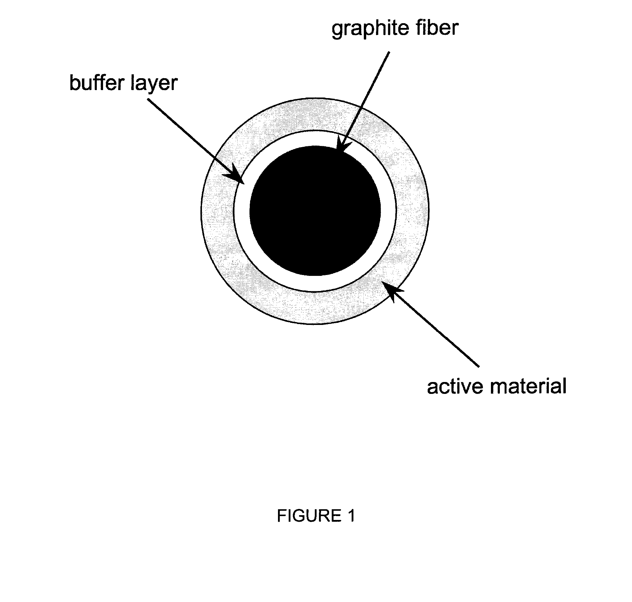
[0020]Thus, it is an advantage of the present invention to provide a durable, lightweight lead-acid battery by reducing weight by replacing lead alloy grids with carbon fibers, and by taking advantage of the large surface area of the fibers.
[0021]It is another advantage to provide a durable, lightweight lead-acid battery by improving durability through engineered buffer layers between carbon fibers and active materials.
[0022]It is yet another advantage to provide a durable, lightweight lead-acid battery by maximizing material utilization through the use of uniform thin active material layers, and by improving charging rates.
[0023]These and other features, aspects, and advantages of the present invention will become better understood upon consideration of the following detailed description, drawings and appended claims.

Problems solved by technology

The low specific energy of lead-acid batteries has limited their use in electric and hybrid-electric vehicle applications and other mobile and portable applications, where the weight of the battery is critical to meeting efficiency goals.
The cycling of positive plates leads to corrosion between the interface of the lead peroxide active material and the grid material (typically a lead alloy).
The combination of expansion, contraction, and corrosion reactions limits the life of the positive plate.
After exposure of positive plate to cycling, the lead peroxide active material can separate from the grid resulting in a loss of electrical continuity at the interface between grid and the active material.

Method used


Image

  • Lightweight, Durable Lead-Acid Batteries
  • Lightweight, Durable Lead-Acid Batteries
  • Lightweight, Durable Lead-Acid Batteries

Examples


examples

[0042]The following Examples have been presented in order to further illustrate the invention and are not intended to limit the invention in any way.

[0043]A buffer layer was synthesized onto graphite fibers. FIG. 3 shows photographs of Ti2PbC synthesized onto graphite fiber. An X-ray diffraction pattern revealed the presence of Pb, Ti2PbC and Pb—Ti compounds (see FIG. 4.) The photographs of FIG. 5 show an inner layer next to the carbon fiber surface consisting of an intimate mixture of fine-grained (20-100 nm) TiC+Ti(Pb)C (Ti:Pb=3:1). The arrows point to several Ti(Pb)C crystals. The photographs of FIG. 6 show a columnar outer layer of TiC+Ti(Pb)C (Ti:Pb=3:1) and an inner layer next to the carbon fiber surface of TiC+Ti(Pb)C (Ti:Pb=3:1). FIG. 7 shows the electrochemical performance of Pb—Ti—C compounds.

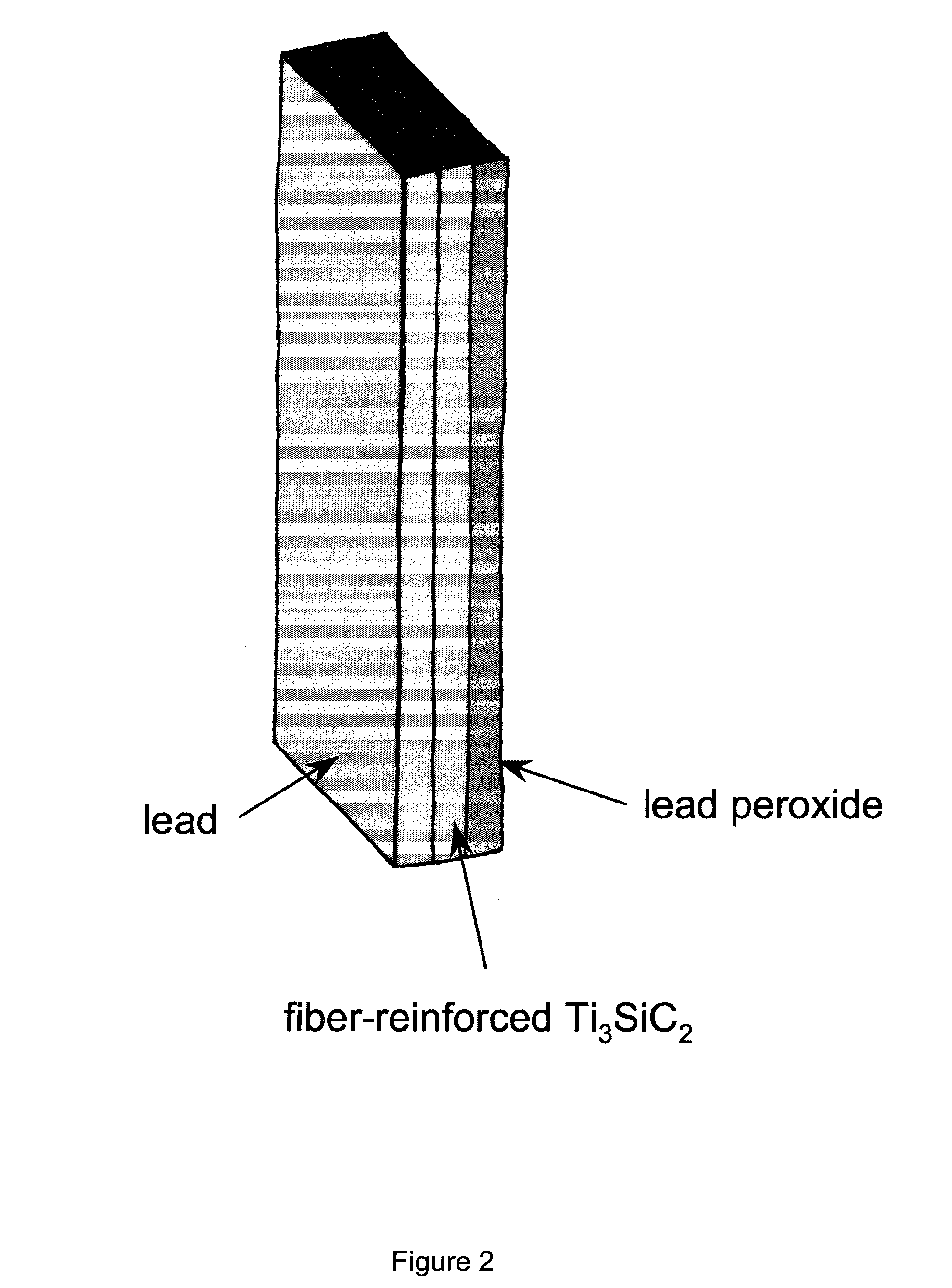
[0044]A battery containing PbO2-coated Ti3SiC2 was prepared. The charge / discharge of the battery containing PbO2-coated Ti3SiC2 is shown in FIG. 8. Both metallic lead and lead peroxid...


PUM

PropertyMeasurementUnit
thicknessaaaaaaaaaa
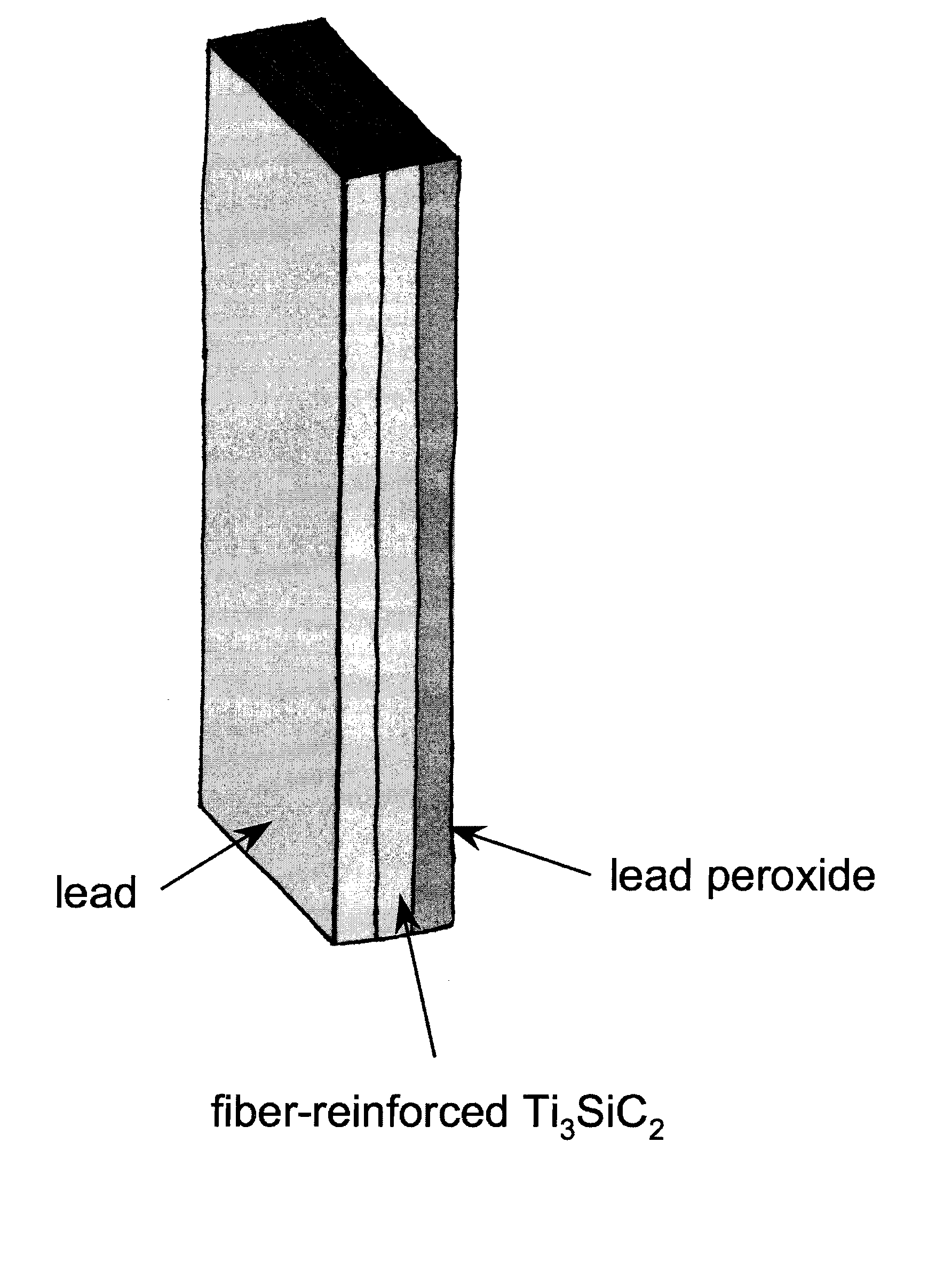
diameteraaaaaaaaaa
densityaaaaaaaaaa

Abstract

A lightweight, durable lead-acid battery is disclosed. Alternative electrode materials and configurations are used to reduce weight, to increase material utilization and to extend service life. The electrode can include a current collector having a buffer layer in contact with the current collector and an electrochemically active material in contact with the buffer layer. In one form, the buffer layer includes a carbide, and the current collector includes carbon fibers having the buffer layer. The buffer layer can include a carbide and/or a noble metal selected from of gold, silver, tantalum, platinum, palladium and rhodium. When the electrode is to be used in a lead-acid battery, the electrochemically active material is selected from metallic lead (for a negative electrode) or lead peroxide (for a positive electrode).

Description

STATEMENT REGARDING FEDERALLY SPONSORED RESEARCH[0001]This invention was made with government support under Contract No. DE-AC05-00OR22725 awarded by the U.S. Department of Energy. The government has certain rights in the invention.CROSS-REFERENCES TO RELATED APPLICATIONS[0002]Not Applicable.BACKGROUND OF THE INVENTION[0003]1. Field of the Invention[0004]This invention relates to a durable, lightweight lead-acid battery. Significant weight savings can be achieved by using carbon fiber structures to fabricate the grid / current collectors, and by maximizing the surface area-to-volume ratio of the active materials. To promote long-term durability, the interfaces between the grid / current collectors and the active materials are tailored with buffer layers, to ensure adhesion and to minimize increases in electrical resistance that might result from the formation of interfacial phases during cyclic charging and discharging.[0005]2. Description of the Related Art[0006]The low specific energy...

Claims


Application Information

Patent Timeline
Patent Type & Authority Applications(United States)
IPC IPC(8): H01M4/14H01M4/36H01M4/16
CPCH01M4/16H01M4/57H01M4/663H01M4/667Y10T29/49115H01M4/73Y02E60/126Y10T29/10H01M4/68Y02E60/10Y02P70/50
Inventor LARA-CURZIO, EDGARAN, KEKIGGANS, JR., JAMES O.DUDNEY, NANCY J.CONTESCU, CRISTIAN I.BAKER, FREDERICK S.ARMSTRONG, BETH L.
Owner UT BATTELLE LLC
Why Eureka
Try Eureka