Legalization of VLSI circuit placement with blockages using hierarchical row slicing

a hierarchical row and blockage technology, applied in the field of physical layout (placement) of logic cells, can solve the problems of large number of cells, difficult computer-aided physical design, and complicated connections between cells, and achieve the effect of efficient handling of the presence of blockages

Active Publication Date: 2009-10-29
SIEMENS PROD LIFECYCLE MANAGEMENT SOFTWARE INC
View PDF9 Cites 36 Cited by
  • Summary
  • Abstract
  • Description
  • Claims
  • Application Information

AI Technical Summary

Benefits of technology

[0014]It is another object of the present invention to provide such a legalizer that more efficiently handles the presence of blockages in the placement region.
[0015]It...

Problems solved by technology

An IC may include a very large number of cells and require complicated connections between the cells.
Due to the large number of components and the details required by the fabrication process for very large scale integrated (VLSI) devices, physical design is not practical without the aid of computers.
However, physical synthesis can take days to complete, and the computational requirements are increasing as designs are ever larger and more gates need to be placed.
After timing optimization, if the cells are moved by a large distance during legalization then it can significantly degrade the performance of the circuit.
However, as VLSI circuits have become more complicated and denser, there has been a steady increase in the presence of various fixed modules or reserved spaces such as power grids, clock components, planned buses or datapaths, hierarchical logic, memory, analog blocks, or propriety (IP) blocks.
As a result, designs today often contain numerous blockages and millions of movable modules.
These fixed modules present a highly fragmented placement region in which the movable modules need to be placed, greatly complicating the legalization problem.
Fractured designs greatly degrade the performance of tr...

Method used


Image

  • Legalization of VLSI circuit placement with blockages using hierarchical row slicing
  • Legalization of VLSI circuit placement with blockages using hierarchical row slicing
  • Legalization of VLSI circuit placement with blockages using hierarchical row slicing

Examples


Embodiment Construction

)

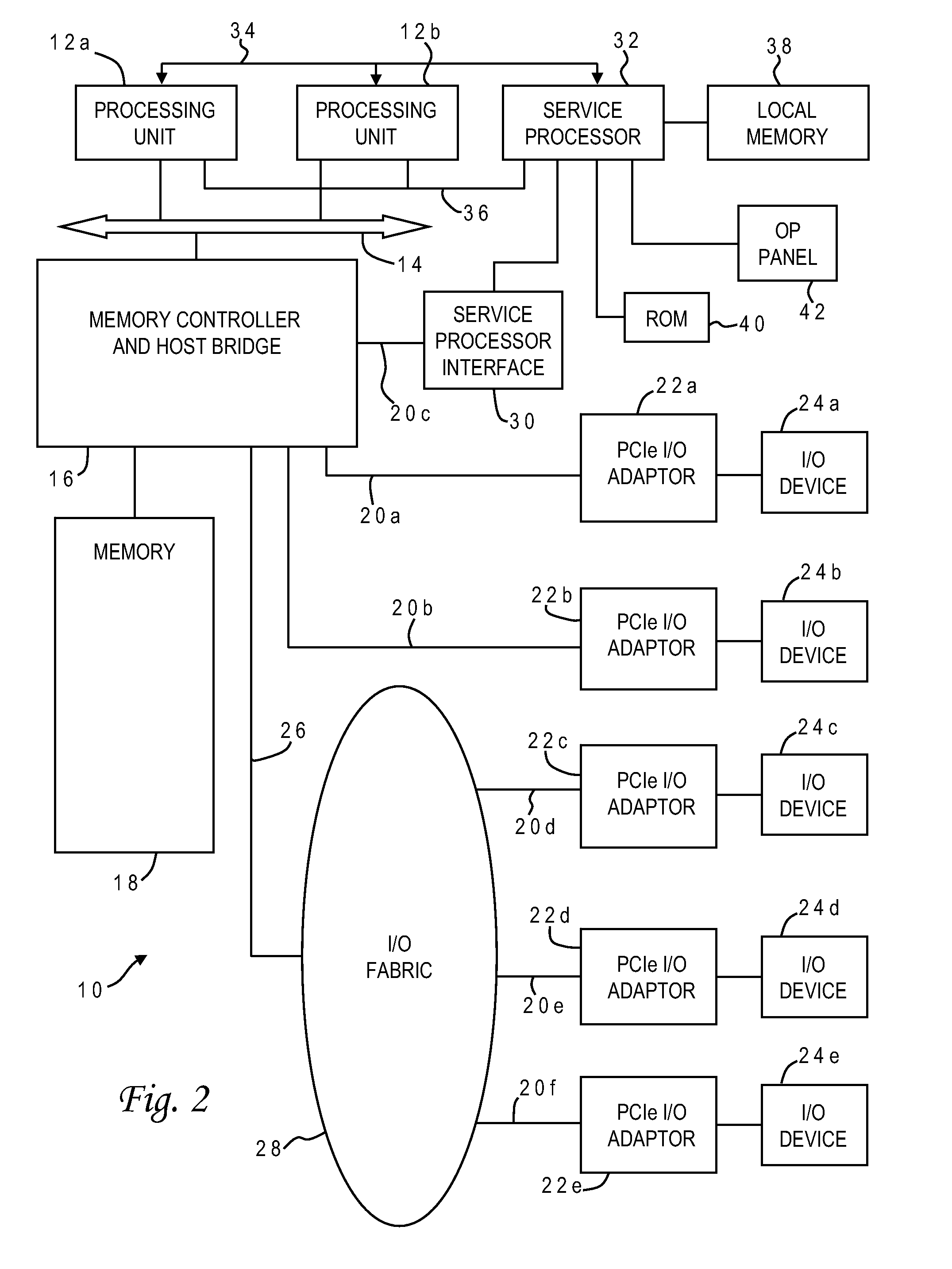
[0027]With reference now to the figures, and in particular with reference to FIG. 2, there is depicted one embodiment 10 of a computer system in which the present invention may be implemented. Computer system 10 is a symmetric multiprocessor (SMP) system having a plurality of processors 12a, 12b connected to a system bus 14. System bus 14 is further connected to a combined memory controller / host bridge (MC / HB) 16 which provides an interface to system memory 18. System memory 18 may be a local memory device or alternatively may include a plurality of distributed memory devices, preferably dynamic random-access memory (DRAM). There may be additional structures in the memory hierarchy which are not depicted, such as on-board (L1) and second-level (L2) or third-level (L3) caches.

[0028]MC / HB 16 also has an interface to peripheral component interconnect (PCI) Express links 20a, 20b, 20c. Each PCI Express (PCIe)link 20a, 20b is connected to a respective PCIe adaptor 22a, 22b, and each PCI...


PUM


Abstract

A hierarchical method of legalizing the placement of logic cells in the presence of blockages selectively classifies the blockages into at least two different sets based on size (large and small). Movable logic cells are relocated first among coarse regions between large blockages to remove overlaps among the cells and the large blockages without regard to small blockages (while satisfying capacity constraints of the coarse regions), and thereafter the movable logic cells are relocated among fine regions between small blockages to remove all cell overlaps (while satisfying capacity constraints of the fine regions). The coarse and fine regions may be horizontal slices of the placement region having a height corresponding to a single circuit row height of the design. Cells are relocated with minimal perturbation from the previous placement, preserving wirelength and timing optimizations. The legalization technique may utilize more than two levels of granularity with multiple relocation stages.

Description

BACKGROUND OF THE INVENTION[0001]1. Field of the Invention[0002]The present invention generally relates to the fabrication and design of semiconductor chips and integrated circuits, and more particularly to the physical layout (placement) of logic cells in an integrated circuit design.[0003]2. Description of the Related Art[0004]Integrated circuits are used for a wide variety of electronic applications, from simple devices such as wristwatches to the most complex computer systems. A microelectronic integrated circuit (IC) chip can generally be thought of as a collection of logic cells with electrical interconnections between the cells, formed on a semiconductor substrate (e.g., silicon). An IC may include a very large number of cells and require complicated connections between the cells. A cell (or module) is a group of one or more circuit elements such as transistors, capacitors, resistors, inductors, and other basic circuit elements grouped to perform a logic function. Cell types ...

Claims


Application Information

Patent Timeline
IPC IPC(8): G06F17/50
CPCG06F17/5072G06F30/392
Inventor ALPERT, CHARLES J.DOTSON, MICHAEL W.NAM, GI-JOONRAMJI, SHYAMVISWANATHAN, NATARAJAN
Owner SIEMENS PROD LIFECYCLE MANAGEMENT SOFTWARE INC
Why Eureka
Try Eureka