Layered polycrystalline diamond

a polycrystalline diamond and diamond technology, applied in the direction of cutting machines, slitting machines, constructions, etc., can solve the problems of reducing or eliminating the effectiveness of cutting elements, and reducing the strength of superhard materials

Active Publication Date: 2009-11-05
SCHLUMBERGER TECH CORP
View PDF114 Cites 65 Cited by
  • Summary
  • Abstract
  • Description
  • Claims
  • Application Information

AI Technical Summary

Benefits of technology

[0006]The plurality of layers may comprise a varying layer thickness or a uniform layer thickness. More specifically, the diamond layer may comprise a thickness between 0.010 and 0.100 inch The plurality of layers may comprise various geometries including inverted cone-shaped, straight, cone-shaped, irregular, or combinations thereof. A volume of the superhard material may comprise 75 to 150 percent of a volume of the substrate. A thickness of at least one layer of the plurality of layers may be as thick as a thickness of the substrate. The diamond layer adjacent the substrate may have a catalyzing material concentration between 5 and 10 percent. The diamond layer at the distal end of the superhard material may have a catalyzing material concentration between 2 and 5 percent. The diamond layer at the distal end of the superhard material may be leached. The leached diamond layer may comprise a catalyzing material concentration of 0 to 1 percent. The superhard material may have a

Problems solved by technology

Such inserts are often subjected to intense forces, torques, vibration, high temperatures and temperature differentials during operation.
As a result, stresses within the structure may begin to form.
Drill bits for example may exhibit stresses aggravated by drilling anomalies during well boring operations such as bit whirl or bounce often resulting in spalling, delamination or fracture of the superhard materia

Method used


Image

  • Layered polycrystalline diamond
  • Layered polycrystalline diamond
  • Layered polycrystalline diamond

Examples


Embodiment Construction

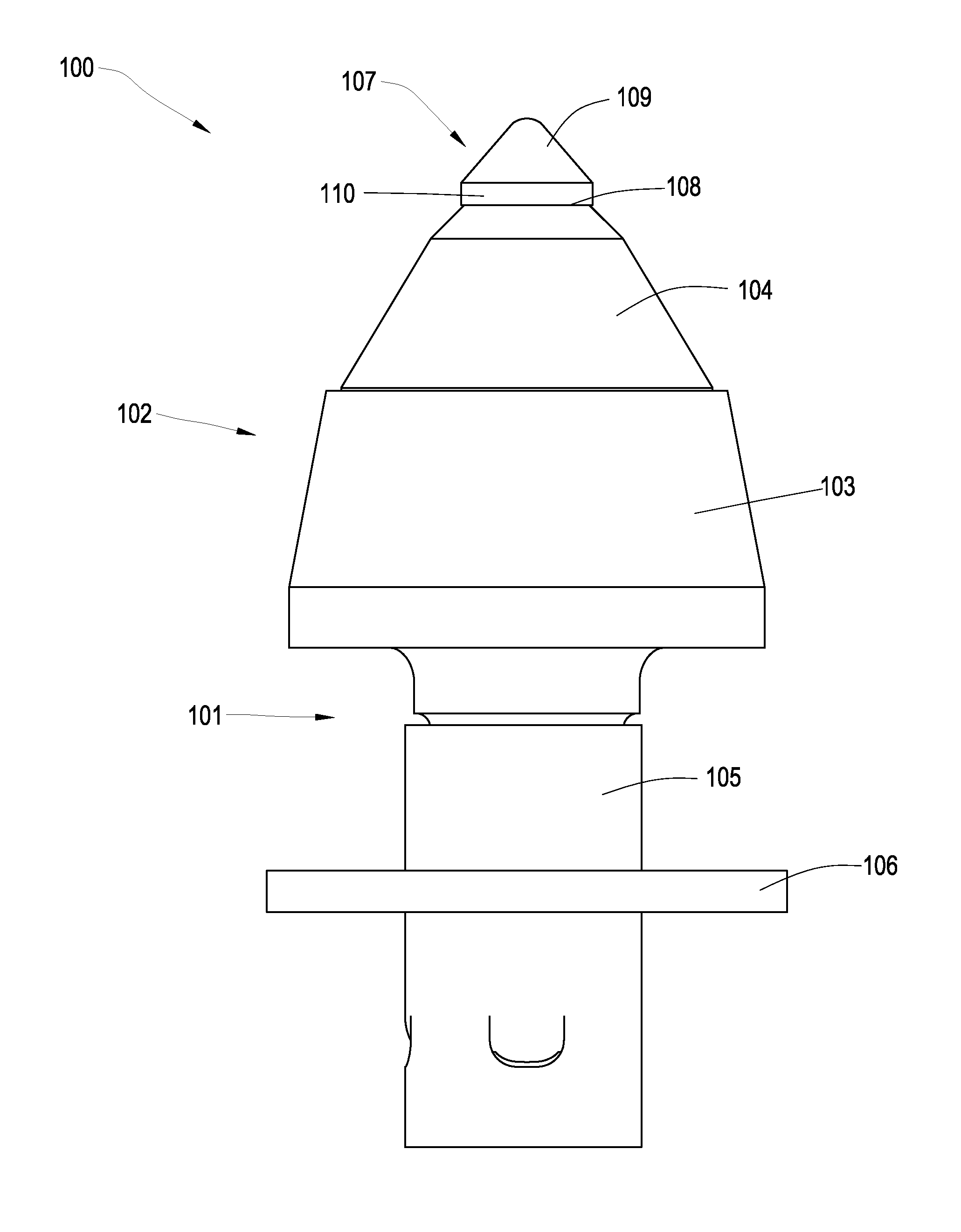
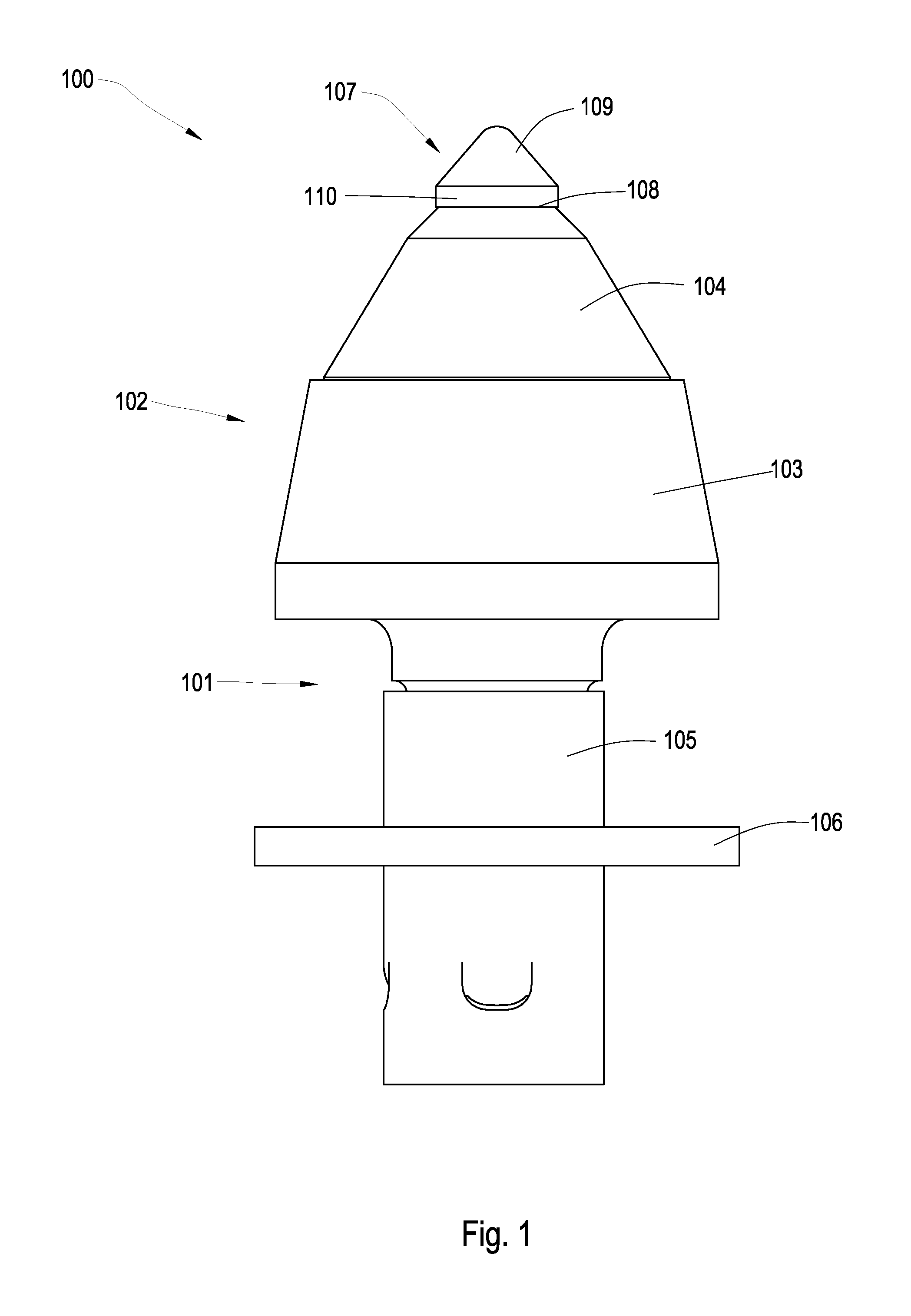
[0024]FIG. 1 is a perspective diagram of an embodiment of a high impact wear resistant tool 100. The tool 100 may be used in machines in mining, asphalt milling, drilling, or trenching industries. The tool 100 may comprise a shank 101 and a body 102, the body 102 being divided into first and second segments 103, 104. The first segment 103 may generally be made of steel, while the second segment 104 may be made of a harder material such as cemented metal carbide. The second segment 104 may be bonded to the first segment 103 by brazing to prevent the second segment 104 from detaching from the first segment 103.

[0025]The shank 101 may be adapted to be attached to a driving mechanism. A protective spring sleeve 105 may be disposed around the shank 101 both for protection and to allow the high impact wear resistant tool to be press fit into a holder while still being able to rotate. A washer 106 may also be disposed around the shank 101 such that when the high impact resistant tool 100 i...


PUM


Abstract

In one aspect of the present invention, a high impact wear resistant tool has a superhard material bonded to a cemented metal carbide substrate at a non-planar interface. The superhard material has a thickness of at least 0.100 inch and forms an included angle of 35 to 55 degrees. The superhard material has a plurality of substantially distinct diamond layers. Each layer of the plurality of layers has a different catalyzing material concentration. A diamond layer adjacent the substrate of the superhard material has a higher catalyzing material concentration than a diamond layer at a distal end of the superhard material.

Description

BACKGROUND OF THE INVENTION[0001]The present invention relates to high impact wear resistant tools that may be used in machinery such as crushers, picks, grinding mills, roller cone bits, rotary fixed cutter bits, earth boring bits, percussion bits or impact bits, and drag bits. More particularly, the invention relates to inserts comprised of a carbide substrate with a non-planar interface and an abrasion resistant layer of superhard material affixed thereto using a high pressure high temperature press apparatus. Such inserts typically comprise a superhard material layer or layers formed under high temperature and pressure conditions, usually in a press apparatus designed to create such conditions, cemented to a carbide substrate containing a metal binder or catalyst such as cobalt. The substrate is often softer than the superhard material to which it is bound. Some examples of superhard materials that high pressure high temperature (HPHT) presses may produce and sinter include ceme...

Claims


Application Information

Patent Timeline
IPC IPC(8): E21C25/04
CPCE21C35/183E21B10/5673E21C2035/1816E21C35/1837E21C35/1835
Inventor HALL
Owner SCHLUMBERGER TECH CORP
Why Eureka
Try Eureka