High average power ultra-short pulsed laser based on an optical amplification system

a laser and optical amplification technology, applied in the field of light amplification, can solve the problems of low material removal rate, subject to pulse aberration and distortion, and impracticality of most applications

Inactive Publication Date: 2009-11-05
RAYDIANCE
View PDF13 Cites 52 Cited by
  • Summary
  • Abstract
  • Description
  • Claims
  • Application Information

AI Technical Summary

Problems solved by technology

Higher pulse powers enable higher material removal rates, but are subject to pulse aberrations and distortions.
Conversely, lower pulse powers result in low material removal rates that render the technique impractical for most applications.

Method used


Image

  • High average power ultra-short pulsed laser based on an optical amplification system
  • High average power ultra-short pulsed laser based on an optical amplification system
  • High average power ultra-short pulsed laser based on an optical amplification system

Examples


Embodiment Construction

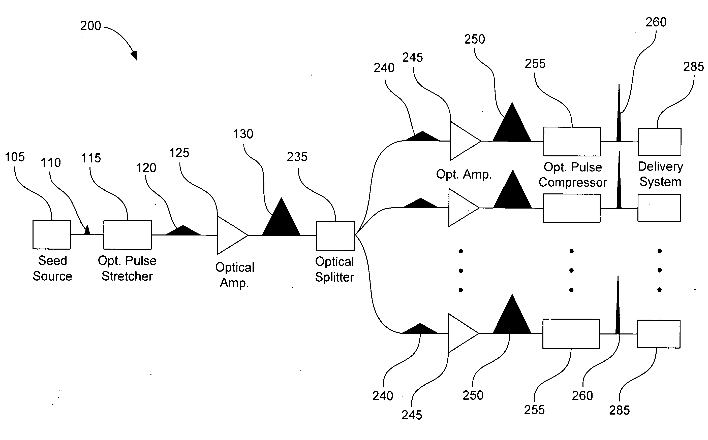
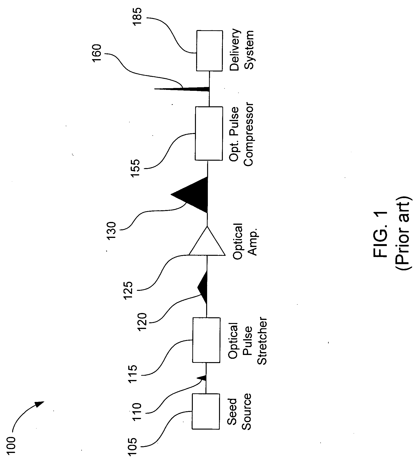
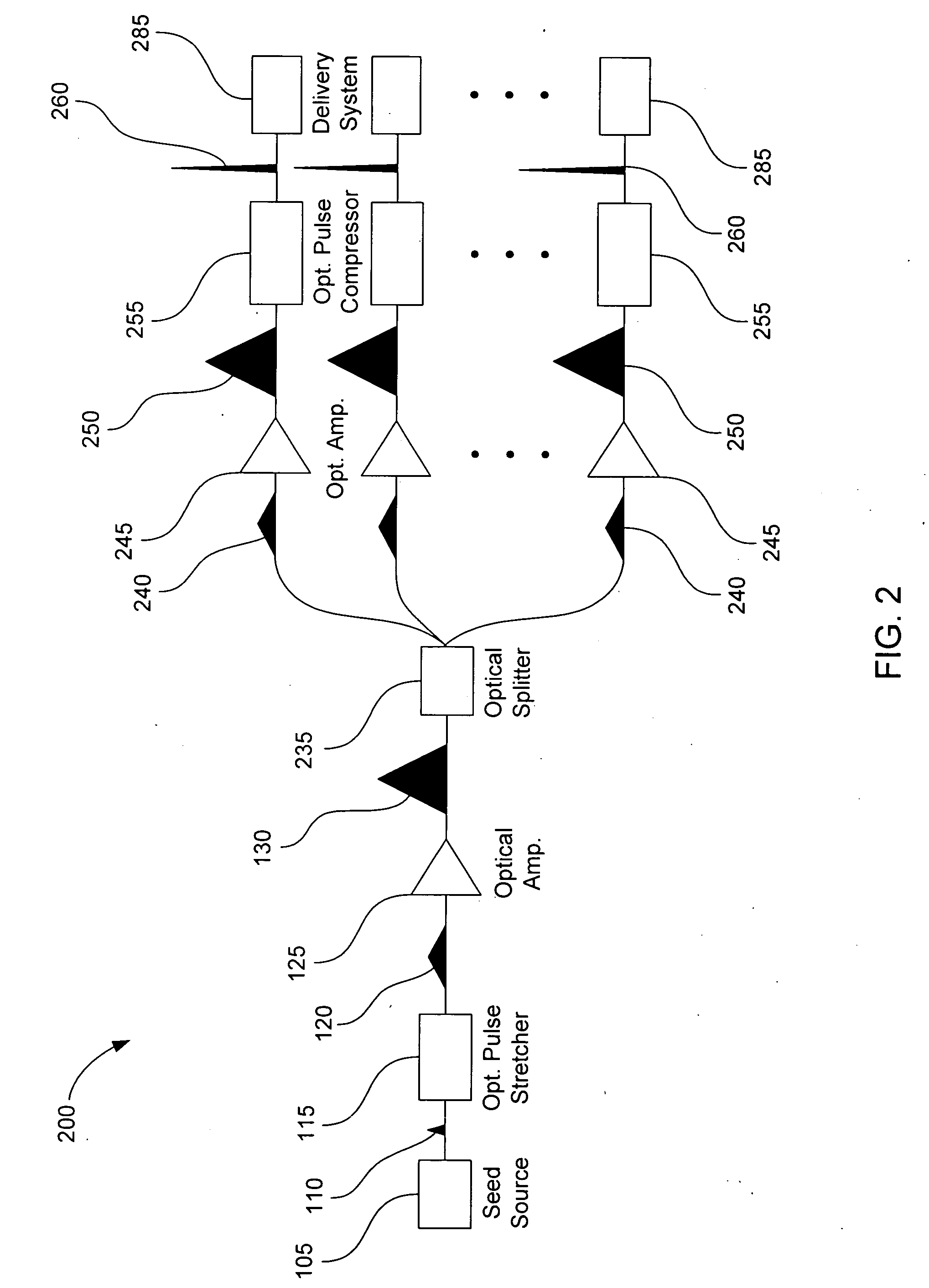
[0016]An ultra-short pulse (USP) laser system emits optical pulses resulting in a very high electric field for an ultra-short short period of time. In this context, “ultra-short” refers to durations in the range of picoseconds (psec, 10−12 seconds) to femtoseconds (fsec, 10−15 seconds). Although the peak power of a USP may be high, the average power contained by the USP may be relatively low, as a result of the pulse duration being ultra-short. FIG. 1 is a block diagram illustrating a typical USP laser system 100, according to various embodiments of the prior art. A seed source 105 can be any light source capable of generating an optical pulse 110 with characteristics of an ultra-short pulse. Light sources with this capability may include, for example, fiber mode-locked lasers, gas lasers (e.g., helium-neon, argon, and krypton), chemical lasers (e.g., hydrogen fluoride and deuterium fluoride), dye lasers, metal vapor lasers (e.g., helium cadmium metal vapor), solid state lasers (e.g...


PUM


Abstract

The present invention includes an apparatus and the method to scale the average power from high power ultra-short pulsed lasers, while at the same time addressing the issue of effective beam delivery and ablation, by use of an optical amplification system.

Description

BACKGROUND OF THE INVENTION[0001]1. Technical Field[0002]The present invention relates generally to the field of light amplification and, particularly to systems useful in athermal ablation.[0003]2. Description of Related Art[0004]An ultra-short pulse (USP) laser emits pulses with a temporal pulse length in the range of picoseconds (psec, 10−12 seconds) to femtoseconds (fsec, 10−15 seconds) resulting in a very high electric field for a short duration of time. Typical techniques for generating these ultra-short pulses are well known. Generally, large systems, such as Ti:Sapphire, are used for generating ultra-short pulses.[0005]USP phenomena were first observed in the 1970's. It was discovered that mode-locking a broad-spectrum laser could produce ultra-short pulses. As produced, an ultra-short pulse has significantly lower power compared to optical pulses having greater temporal lengths. When high-power, ultra-short pulses are desired, the pulses are intentionally lengthened tempora...

Claims


Application Information

Patent Timeline
Patent Type & Authority Applications(United States)
IPC IPC(8): H01S3/00
CPCH01S3/0057H01S3/06741H01S3/2383H01S3/2325H01S3/06754
Inventor WAARTS, ROBERT G.BOOTH, TIMOTHY J.
Owner RAYDIANCE
Why Eureka
Try Eureka