Method for growing carbon nanowalls

a carbon nanowall and nanotube technology, applied in the direction of liquid-gas reaction process, chemical/physical/physicochemical process, chemical apparatus and processes, etc., can solve the problems of inability inability to use non-silicon substrates and glass as substrates to grow carbon nanowalls, and inability to make carbon nanowalls

Inactive Publication Date: 2009-11-05
GHOANNEVISS MAHMOOD +2
View PDF1 Cites 21 Cited by
  • Summary
  • Abstract
  • Description
  • Claims
  • Application Information

AI Technical Summary

Benefits of technology

[0011]There is pressure in hot chamber and gas is passing under atmospheric pressure and there is no vacuum. Additional gas entered into hot and reaction chamber is gone out. Some effective factors for growing carbon nanowalls and changing structures are temperature of reaction chamber, type of catalyst on the glass substrate, ratio of Hydrocarbon and non hydrocarbon gases and reaction time. This is an advantage by which carbon nanowalls with special properties (thickness, height, growth density, monotony and distribution) are established.
[0013]Both regions are activated by warming around the chamber. To do it, thermal elements covered by ceramic are employed which make heat by applying electricity. According to division degree technique (quantity of established radicals) radical source can be controlled by changing temperature or electricity power entered into thermal elements. Other advantage of same technique is that feeding speed of radical sources inside the chamber for growing carbon nanowalls can be controlled.
[0022]In the method, base material (glass) has covered by various catalysts in thin layers in nanometer. Catalyst layers are settled on each other in 2 layers or separately. The present invention discloses a method for producing carbon nanowalls on the glass substrate under atmospheric pressure by CVD method. Metal catalysts cause to produce kind of carbon nanowalls. This method has useful arrangement on the base material (glass). Since 2 dimensional nanostructures (carbon nanowalls) have developed on the glass base material, these have some advantages and can be applied for different demands. Recent invention provides apparatus for establishing carbon nanowalls on the base material which is glass. Experiment is easy and done under atmosphere pressure. Apparatus includes a chamber in which material is radicalized and nanostructures are made and carbon source material and non-carbon materials are entered. Energy source for radicalizing non-hydrocarbon materials and carbon source material is out of chamber and this source leads to heat inside the chamber and to make the radical materials. Before entering into the chamber, materials are mixed together in other one without heat. Additional materials entered into the reaction chamber are driven out under atmosphere pressure. Above mentioned materials are suitable for this method.

Problems solved by technology

Accordingly, if there is no silicon substrate, carbon nanowalls cannot be grown.
There is no technique for using non-silicon substrates and glass as substrate to grown carbon nanowalls.
So if there are no Hydrocarbon gases including Fluorine and Hydrogen, it is not possible to make carbon nanowalls.
So if the substrate and catalyst is not Silicon and Iron Nickel respectively, carbon nanowalls cannot be formed.

Method used


Image

  • Method for growing carbon nanowalls
  • Method for growing carbon nanowalls
  • Method for growing carbon nanowalls

Examples


experiment 1

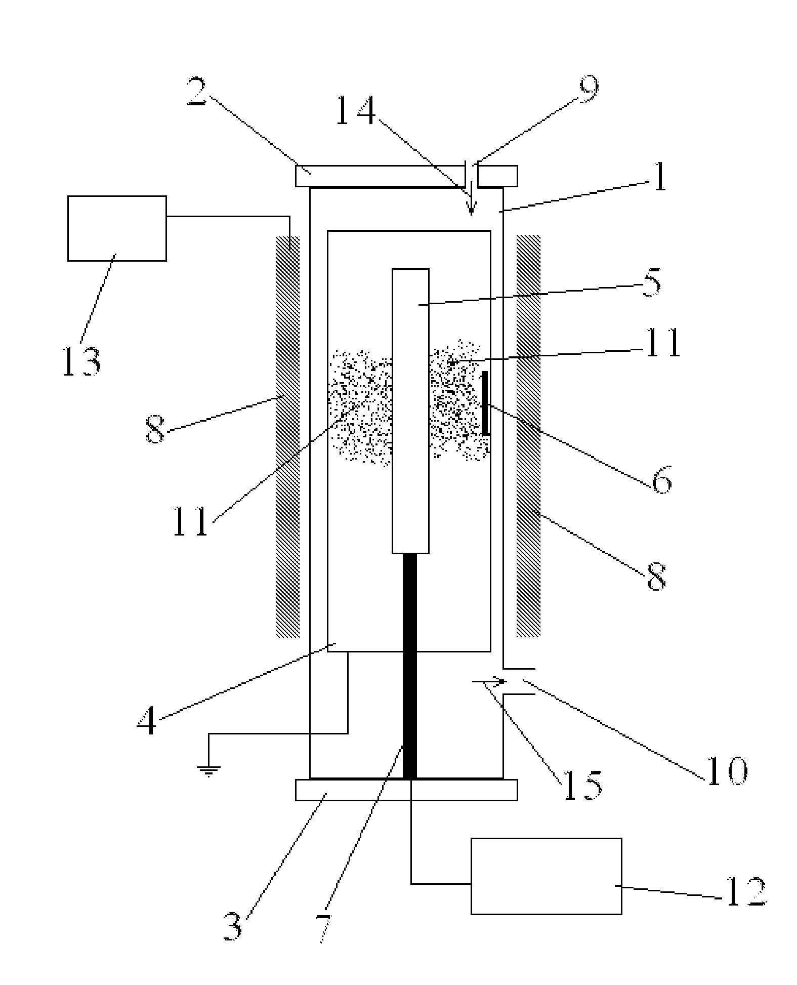
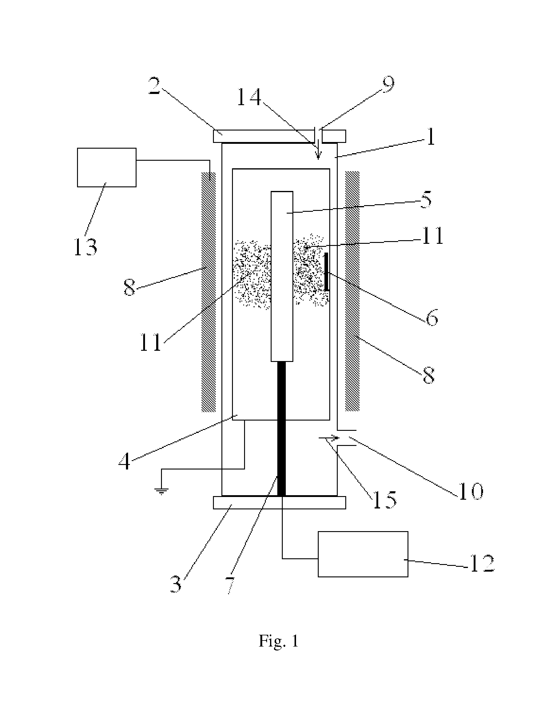
[0085] This experiment aims to mark the layer of catalyst aluminum (Al) on the glass base material 6 which is done by apparatus No. 1. In this experiment, base material 6 (substrate) is cleaned by using acetone, alcohol and distilled and deionized water for 10 minutes in ultrasonic bath to remove all impurities. Then base material 6 are settled in apparatus No. 1 on the anode 4 and cathode 5 iron is located on itself place. Then the chamber is blocked by using two flanges 2 and 3. The set will be prepared to make plasma. To do it, at the first, there should be the vacuum in the chamber 1 up to 10−5 torr and then to make plasma and ionized gases, Argon gas (Ar) is entered into the system through pore 9 and path 14 to reach the chamber's vacuum 0.03 torr. In this case, to concentrate the plasma in the plasma making region 11, there will be a field by using magnetic field 8 arranged by source 13. At same time, cathode 5 receives voltage by source 12 during 3 minutes and current 200 mA ...

experiment 2

[0086] this is same as experiment 1 except for using cathode 5 Iron (Fe) instead of using cathode 5 Iron.

experiment 3

[0087] in this experiment like experiment 1, same system is applied except for marking the second layer on the base material 6 to have the base materials 6 with two different catalyst layers. So base material 6 marked by iron is settled in apparatus No. 1 and then we continue operation same as experiment 1 to have the base material 6 with two different layers therefore we will have the base material 6 with two nano-layers (aluminum layer on the iron layer) in the presence of argon gas.


PUM

PropertyMeasurementUnit
heightaaaaaaaaaa
lengthaaaaaaaaaa
diameteraaaaaaaaaa

Abstract

A method for growing carbon nanowalls on a base material is disclosed. The method comprises mixing a predetermined amount of a hydrocarbon gas with a predetermined amount of at least one non hydrocarbon gas; placing said base material in a reaction chamber having a first portion and a second portion, first portion is extended from a first end of reaction chamber to first end of base material; creating a radical in reaction chamber which comprises a hydrocarbon radical and a non hydrocarbon radical; applying the radical to the base material; and growing carbon nanowalls on said base material based on said hydrocarbon radical.

Description

SPONSORSHIP STATEMENT[0001]The present invention is sponsored by Iranian National Science Foundation for international filing.FIELD OF THE INVENTION[0002]The present invention is related to a method for producing nanostructures containing carbon, in particular to create nanowalls under atmospheric pressure without making vacuum and plasma.BACKGROUND OF THE INVENTION[0003]There are kinds of known nanostructures (carbon nanostructures) generally including carbon. Some examples of carbon nanostructures are Fullerene and carbon nano-tubes. Other carbon nanostructures called as carbon nanowalls and in which carbon nanowalls have produced by plasma method and also Silicon is applied as substrate. A method for producing carbon nanowalls is applying plasma and CH4 and H2 also Fluorine Hydrocarbons and or Fluorine and Hydrogen Hydrocarbons are applied.[0004]Some problems should be resolved by invention[0005]Some of documents show that the carbon nanowalls are grown on silicon substrate. Acco...

Claims


Application Information

Patent Timeline
Patent Type & Authority Applications(United States)
IPC IPC(8): D01F9/12B01J8/02
CPCB01J19/088B01J2219/083B01J2219/0869B01J2219/0871C01B31/0293B01J2219/0892B01J2219/0894B82Y30/00B82Y40/00B01J2219/0875C01B32/18
Inventor GHOANNEVISS, MAHMOODALIZADEH ESLAMI, PARVINNASIRI LAHEGHI, SAEED
Owner GHOANNEVISS MAHMOOD
Why Eureka
Try Eureka