Solar cell module

a solar cell and module technology, applied in the field of solar cell modules, can solve the problems of reducing and reducing the reliability of the module, so as to suppress the reduction of the output of the module and improve the reliability

Inactive Publication Date: 2009-11-12
SANYO ELECTRIC CO LTD
View PDF9 Cites 9 Cited by
  • Summary
  • Abstract
  • Description
  • Claims
  • Application Information

AI Technical Summary

Benefits of technology

[0013]The present invention can provide a solar cell module which suppresses the reduction in the module output and improves the reliability.

Problems solved by technology

However, the thermally damaged resin still remains in the interface between each bus bar electrode 10 and the corresponding wiring member 70 in the conventional solar cell module.
This reduces the module output, and serves as a factor for reducing the reliability of the module.

Method used


Image

  • Solar cell module
  • Solar cell module
  • Solar cell module

Examples


examples

[0045]Hereinafter, a thin-film solar cell module acceding to the present invention will be specifically described with reference to Example. However, the present invention is not limited to Example illustrated below, and thus can be carried out appropriately while being modified without departing from the gist thereof.

example

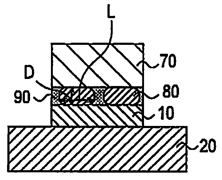
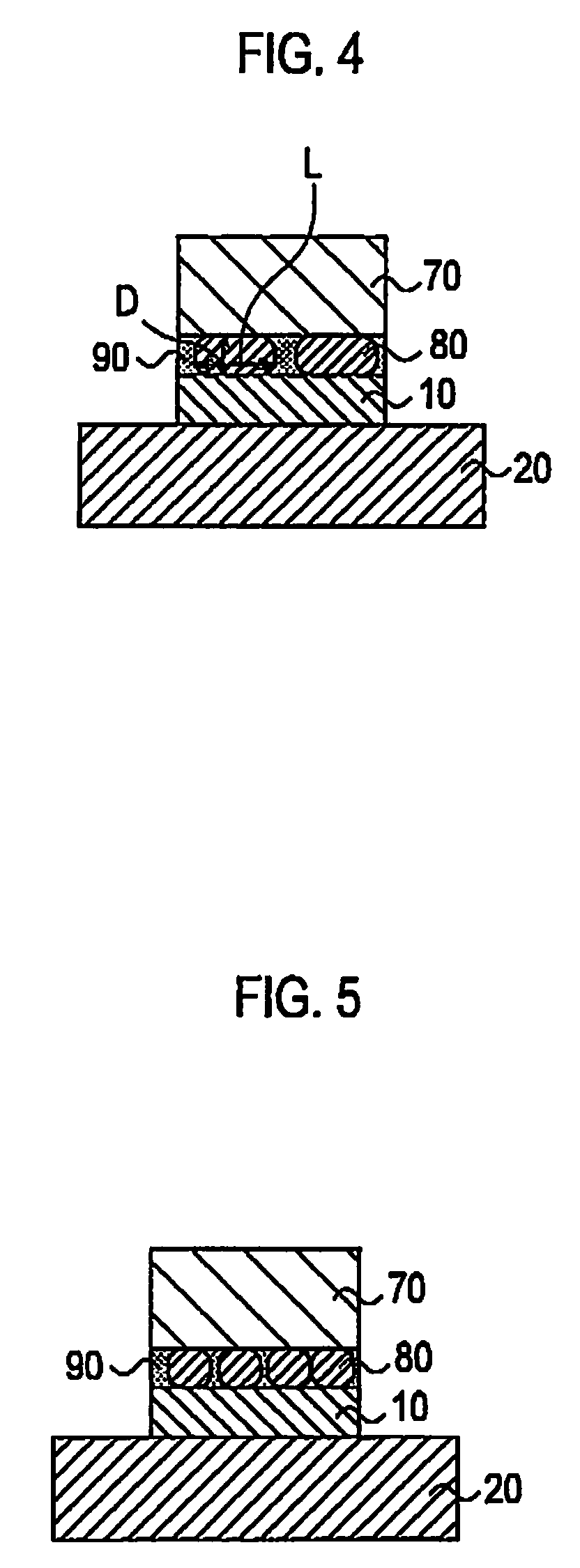
[0046]As a solar cell according to Example of the present invention, a solar cell shown in FIG. 4 was manufactured as follows. The solar call according to Example is a HIT solar cell

[0047]Firstly, a resin made of an epoxy resin, an urethane resin, and the like was mixed with silver particles of approximately 1-μmφ spherical powders and approximately 10-μmφ flake powders at a ratio of 20:80 to 10:90 wt % to thereby prepare a paste whose viscosity was adjusted with an organic solvent in an amount of approximately 0.5 to 5% relative to the entire content. This paste was patterned into a comb-shape on a solar cell 20 by a screen-printing method. The paste is hardened in conditions of 200° C. for 1 hour, and a collecting electrode including bus bar electrodes 10 was formed.

[0048]Then, a resin made of an acrylic resin and the like serving as an adhesive layer was mixed with approximately 20-μmφ spherical aluminum particles at a ratio of 95:5 to 80:20 wt % to thereby prepare a paste whose ...


PUM


Abstract

In a solar cell module, a plurality of solar cells are arranged between a front-surface protection member and a back-surface protection member, and electrodes of the plurality of solar cells is electrically connected to each other by a wring member. The solar cell module includes an adhesive layer including a resin 90 and a plurality of conductive particles 80, between the electrodes 10 and the wiring member 70. Each conductive particle 80 has a flattened shape that a maximum thickness D in a plane perpendicular to a solar cell 20 is smaller than a maximum length L in a plane parallel to the solar cell 20. Both ends of each conductive particle 80 in a thickness direction are respectively in contact with one of the electrodes 10 and the wiring member 70.

Description

TECHNICAL FIELD[0001]The present invention relates to a solar cell module in which a plurality of solar cells are arranged between a front-surface protection member and a back-surface protection member, and in which electrodes of the plurality of solar cells are electrically connected to each other by a wiring member.BACKGROUND ART[0002]Conventionally, a solar cell module includes a plurality of solar cells sealed in a sealing member between a front-surface protection member and a back-surface protection member. The solar cells are electrically connected to each other by wiring members made of a conductive material such as copper foil. The front-surface protection member is made of a translucent material such as a glass, a translucent plastic or the like. The back-surface protection member is made of, for example, a polyethylene terephthalate (PET) film. The sealing member is made of a translucent material such as ethylene vinyl acetate (EVA).[0003]In this respect, to manufacture a ...

Claims


Application Information

Patent Timeline
Patent Type & Authority Applications(United States)
IPC IPC(8): H01L31/042
CPCH01L31/0512Y02E10/50
Inventor YOSHIMINE, YUKIHIROOKAMOTO, SHIGEYUKITSUNOMURA, YASUFUMININOMIYA, KUNIMOTO
Owner SANYO ELECTRIC CO LTD
Why Eureka
Try Eureka