Methods and systems for calibration of RFID sensors

Active Publication Date: 2009-11-12
WESTINGHOUSE AIR BRAKE TECH CORP
View PDF27 Cites 286 Cited by
  • Summary
  • Abstract
  • Description
  • Claims
  • Application Information

AI Technical Summary

Benefits of technology

[0005]In some embodiments a method for calibration of an RFID sensor used in manufacturing and monitoring systems is provided and comprises measuring impedance of an RFID sensor antenna, relating the measurement

Problems solved by technology

However, the acceptance of disposable monitoring technologies is hindered by the absence of RFID sensors having the degree of sci

Method used


Image

  • Methods and systems for calibration of RFID sensors
  • Methods and systems for calibration of RFID sensors
  • Methods and systems for calibration of RFID sensors

Examples


example 1

Calibration Based on Measurements of Complex Impedance

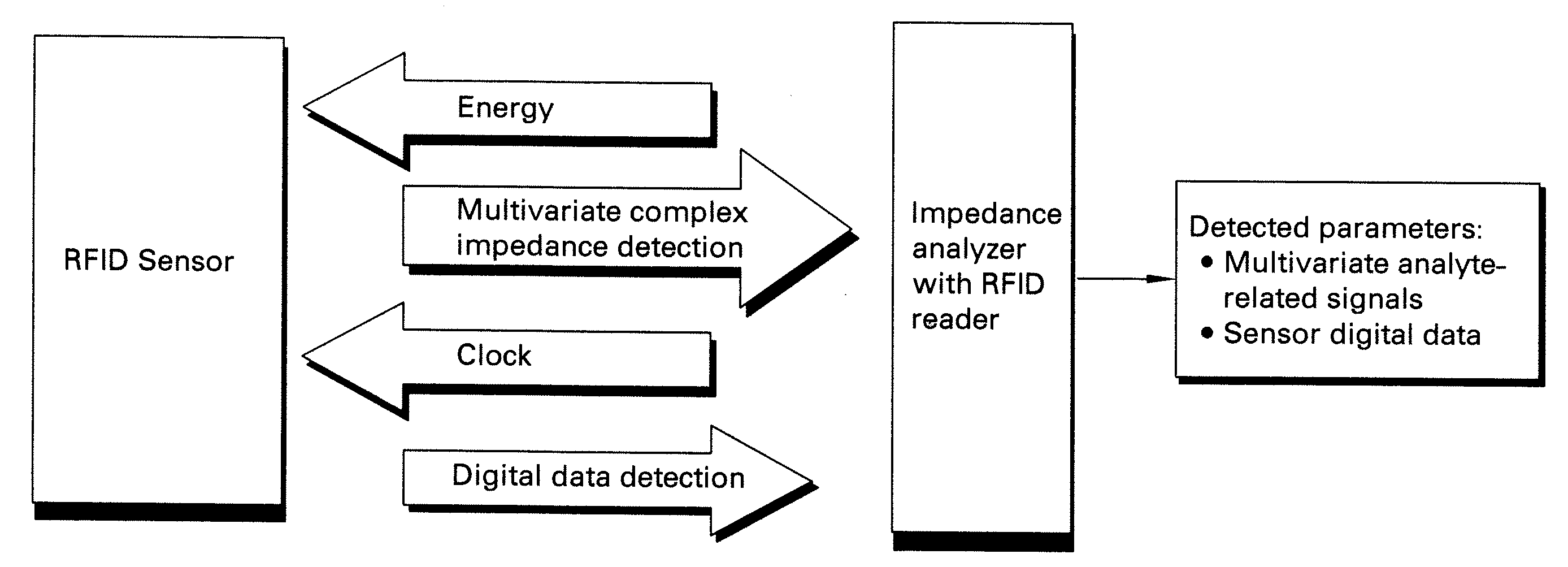
[0064]Passive 13.56 MHz RFID tags (Texas Instruments) were used for temperature sensing and for demonstration of the disclosed calibration methods. Digital ID of the RFID sensors was read with a Skytek reader. Seven RFID sensors were used with the read IDs shown in Table 1.

TABLE 1Digital IDs of the employed RFID sensorsSensorNumberDigital IDCommentsS1E007 000 0219 24E9Replicate measurements (n = 4) oftemperature responseS2E007 000 0219 24E8Replicate measurements (n = 2) oftemperature responseS3E007 000 0219 24E3No complex impedance measurementsdoneS4E007 000 0219 24E7Replicate measurements (n = 2) oftemperature response, used forblind calibrationS5E007 000 0219 24E5Replicate measurements (n = 2) oftemperature responseS6E007 000 0219Replicate measurements (n = 2) of24DAtemperature response

[0065]Measurements of the complex impedance of the RFID sensor were performed with a network analyzer (Model E5062A, Agilent Technologies) and a...

example 2

Measurement of Multiple Parameters Using a Single RFID Sensor

[0071]A single RFID sensor may be used to independently determine more than one parameter. A Texas Instruments RFID tag was adapted for sensing of temperature and solution conductivity by laminating the RFID tag to a polymer film. Measurements of the complex impedance of the resulting RFID sensor were performed with a network analyzer (Model E5062A, Agilent Technologies, Inc. Santa Clara, Calif.) under computer control using LabVIEW. The network analyzer was used to scan the frequencies over the range of interest and to collect the complex impedance response from the RFID sensors. Adding NaCl salt into a vessel to which the RFID sensor was attached produced solution conductivity changes. Positioning the entire vessel and the RFID sensor into an environmental chamber where the temperature was incrementally increased from 5 to 60° C. changed the temperature.

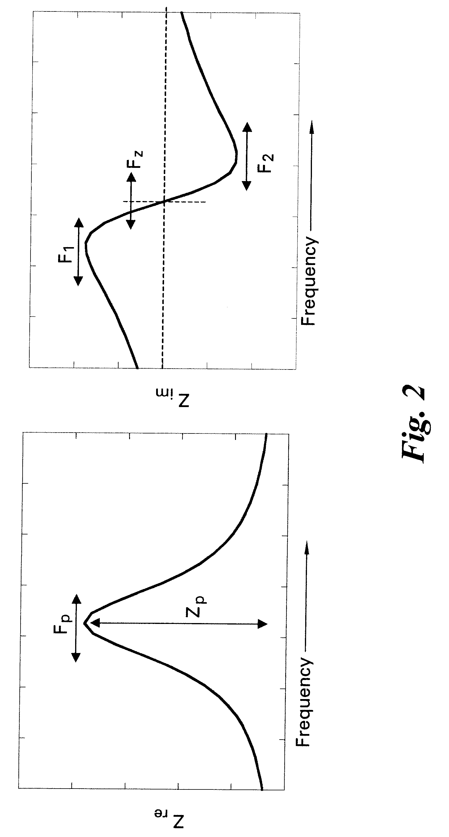
[0072]FIG. 12A shows variations in the measured responses (Fp and Zp...

example 3

Discrimination of Chemical and Physical Measured Parameters Using a Single Complementary RFID Sensor

[0073]The operation of a complementary sensor that exhibits a simultaneous resistance and capacitance change can be used to discriminate between different parameters of interest. These parameters of interest affect the sensor response in diverse ways, such that it is possible to selectively measure one or more parameters

[0074]A combination humidity and temperature RFID sensor was fabricated by attaching a complementary sensor to an RFID tag. A humidity sensor (Vaisala Inc.) was attached to a Texas Instruments RFID tag across its antenna. The humidity sensor from Vaisala Inc. is a capacitor structure filled with a humidity sensitive polymer. The dielectric property of the humidity sensitive polymer changes as a function of humidity. However, these changes are also temperature sensitive. Thus, if a single response is measured from the RFID sensor, temperature and humidity effects on the...


PUM


Abstract

Methods and systems for calibration of RFID sensors used in manufacturing and monitoring systems are provided. The methods include measuring impedance of an RFID sensor antenna, relating the measurement of impedance to one or more parameters (such as physical, chemical and biological properties), computing one or more analytical fit coefficients, and storing the one or more analytical fit coefficients on a memory chip of the RFID sensor. Measuring impedance of the RFID sensor may comprise measuring complex impedance which involves measuring complex impedance spectrum, phase angle and magnitude of the impedance, at least one of frequency of the maximum of the real part of the complex impedance, magnitude of the real part of the complex impedance, zero-reactance frequency, resonant frequency of the imaginary part of the complex impedance, and antiresonant frequency of the imaginary part of the complex impedance. Also provided are manufacturing or monitoring systems comprised of an RFID sensor wherein the RFID sensor comprises, a memory chip, an antenna, and a sensing film wherein analytical fit coefficients are stored on the memory chip to allow calibration of the RFID sensor. Also provided are manufacturing or monitoring systems comprised of an RFID sensor wherein the RFID sensor comprises, a memory chip, an antenna, and a complementary sensor attached to the antenna where the complementary sensor in a pre-calibrated fashion predictably affects the impedance of the antenna.

Description

BACKGROUND[0001]The invention relates generally to radio frequency identification (RFID) sensors used in manufacturing and monitoring systems comprised of single use or multi-use components, and more particularly to a system and method for calibrating the RFID sensors.[0002]Single use, disposable, equipment and components have gained significant interest from the manufacturing community especially the biopharmaceutical, food, beverage, and packaging industries. Single use, disposable monitoring equipment has gained significant interest also from the monitoring community, especially first responders. Single use components offer flexibility, mobility, overall process efficiency as well as reduction in cleaning and sterilization protocols, lower risk of cross-contamination, and reduced manufacturing capital cost. Full ranges of single use, disposable technologies for biopharmaceutical production are commercially available for simple operations such as buffer storage and mixing and are ...

Claims


Application Information

Patent Timeline
IPC IPC(8): G08B13/22
CPCG06K7/0095G06K19/0723G06K19/0716G01N33/0006G01N33/0073
Inventor POTYRAILO, RADISLAV ALEXANDROVICHMORRIS, WILLIAM GUY
Owner WESTINGHOUSE AIR BRAKE TECH CORP
Why Eureka
Try Eureka