HVDC system and method to control a voltage source converter in a HVDC system

a voltage source converter and hvdc technology, applied in power conversion systems, electric power transfer ac networks, circuit arrangements, etc., can solve problems such as difficult power restoration after a wide-area power outage in an ac network or ac grid, uneconomic to provide such a large standby capacity at each station, and difficult process of restoring power after an outag

Active Publication Date: 2009-11-12
HITACHI ENERGY SWITZERLAND AG
View PDF10 Cites 33 Cited by
  • Summary
  • Abstract
  • Description
  • Claims
  • Application Information

AI Technical Summary

Benefits of technology

[0030]Simulation of a restoration of a grid has demonstrated that with control equipment according to the invention, stable AC voltage and frequency are obtained under different AC network conditions, from passive load over a weak AC system with little generation up to a strong AC system with all power generation restarted.

Problems solved by technology

Restoring power after a wide-area power outage in an AC network or AC grid can be difficult.
It is, however, uneconomic to provide such a large standby capacity at each station, so black-start power must be provided over the electrical transmission network from other stations.
To restore the power after an outage is not an easy process.
Small disturbances are continually occurring while the system is weak and fragile during the restoration process, and the grid will experience different conditions, from a dead network over a variety of weak network conditions to a normal strong AC network.
When a converter is connected to an island network with only generation, for instance a windfarm, or only consumption, or the mixture of both, it will be very difficult to predict the active power and reactive power.
It will thus be difficult to determine a desired active power Pref and a desired reactive power Qref and it will be unpractical to control them.
When a converter is connected to a dead electric AC network, i.e., no power supply at all, the above described known control system will fail to work, because there is no AC voltage to synchronize for the PLL, and the current control will not work as the current is determined naturally by the connected load.
When a converter is connected to a very weak electric AC network, i.e., the existing short circuit power in the network is approximately equal to or less than the converter rating, it is very difficult for the above described known control system to maintain the stability, as the weak AC network gives a more oscillating AC bus voltage, which leads to the oscillating of the PLL and current control as both systems use the AC bus voltage as input.

Method used


Image

  • HVDC system and method to control a voltage source converter in a HVDC system
  • HVDC system and method to control a voltage source converter in a HVDC system
  • HVDC system and method to control a voltage source converter in a HVDC system

Examples


Embodiment Construction

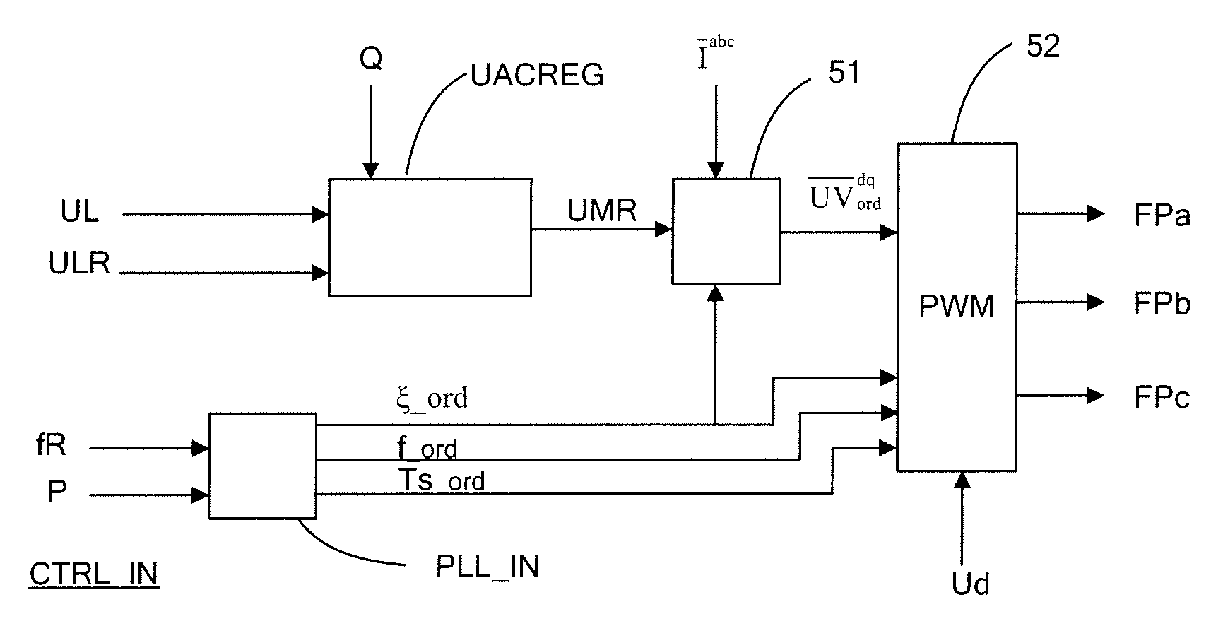
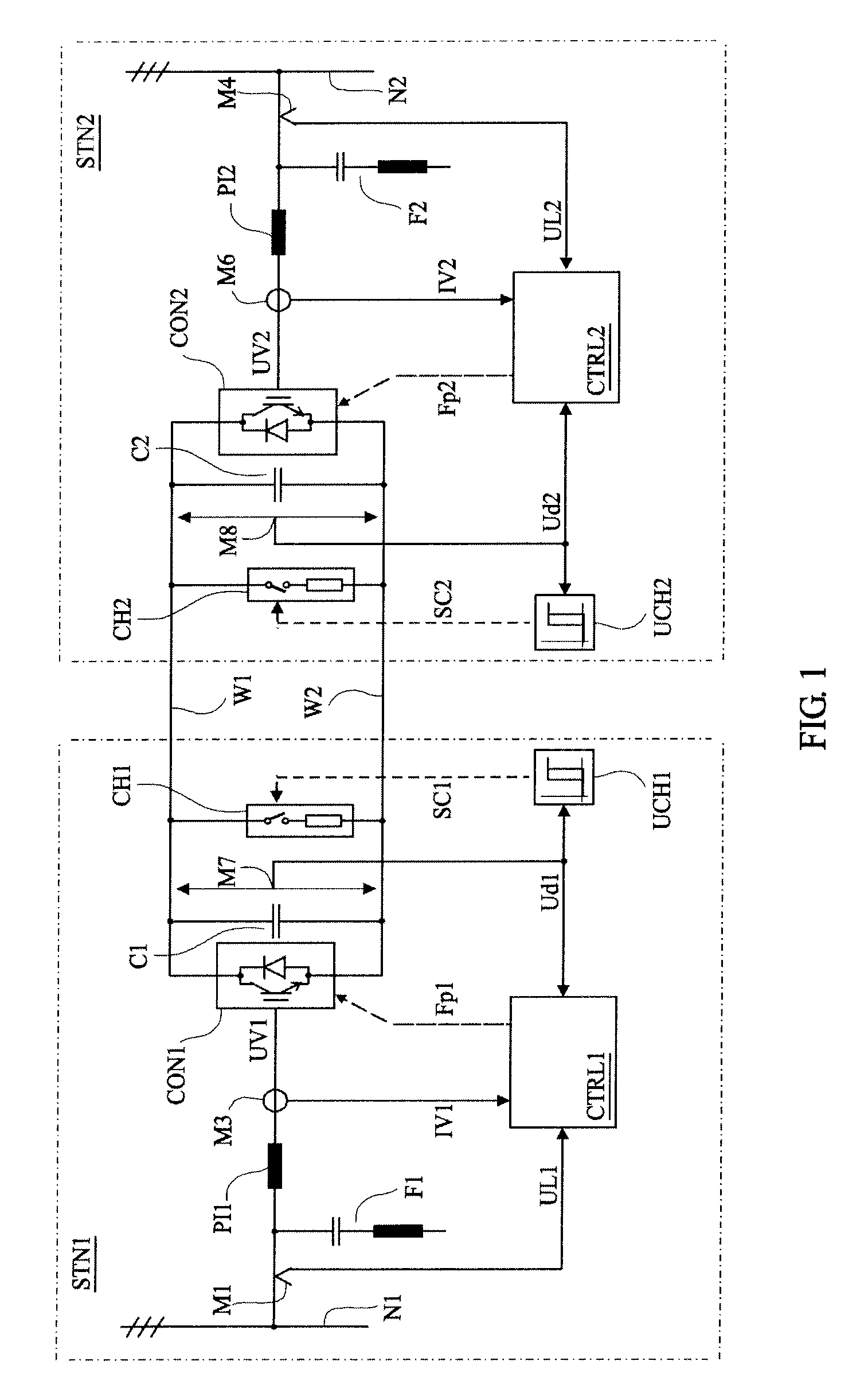
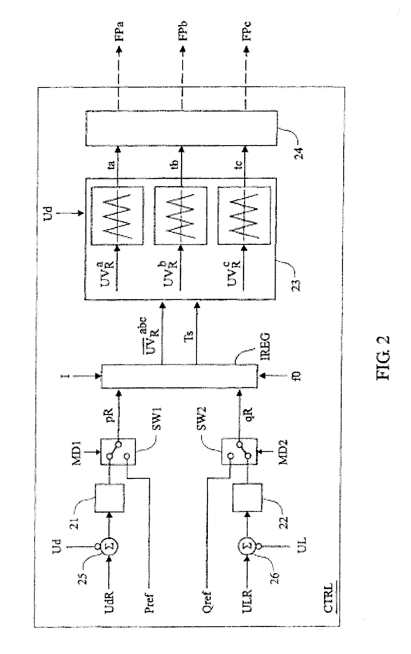
[0039]The block diagrams to be described in the following can be seen both as signal flow diagrams and block diagrams of control equipment. The functions to be performed by the blocks shown in the block diagrams may in applicable parts be implemented by means of analogue and / or digital technique in hard-wired circuits, but preferably as programs in a microprocessor. It shall be understood that although the shown blocks are mentioned as members, filters, devices etc. they are, in particular where their functions are implemented as software for a microprocessor, to be interpreted as means for accomplishing the desired function. Thus, as the case may be, the expression “signal” can also be interpreted as a value generated by a computer program and appearing only as such. Only functional descriptions of the blocks are given below as these functions can be implemented in manners known per se by persons skilled in the art.

[0040]Variables appearing in the control equipment shown in the fig...


PUM


Abstract

A method to control a voltage source converter in a HVDC system includes controlling a frequency and a voltage amplitude of an AC voltage generated by the voltage source converter independently of the conditions in an AC network connected to the voltage source converter. The method is performed by a control unit of an HVDC system. The method may form a basis of a method to black start an AC network. The AC network includes transmission lines and is connected to at least two AC power stations. One of the at least two AC power stations is connected via a HVDC system to the AC network.

Description

TECHNICAL FIELD[0001]The invention relates to a method to control a voltage source converter in a high voltage direct current (HVDC) system and to a HVDC system.BACKGROUND OF THE INVENTION[0002]A HVDC system comprises a first and second converter station each containing a voltage source converter (VSC) for transferring electric power from a first alternating current (AC) network to a second AC network.[0003]Voltage source converters (VSC) are not only used in high voltage direct current (HVDC) systems, but also for example as Static Var Compensators (SVC). In the HVDC application, the voltage source converter is connected between a direct current (DC) link and an AC network, and in the application as Static Var Compensator, the voltage source converter is connected between a direct voltage source and an AC network. In both these applications, the voltage source converter must be able to generate an AC voltage of the same frequency as that of the AC network. The reactive and the acti...

Claims


Application Information

Patent Timeline
Patent Type & Authority Applications(United States)
IPC IPC(8): H02J3/36
CPCH02J3/36H02M5/40Y02E60/60H02M7/797
Inventor JIANG-HAFNER, YING
Owner HITACHI ENERGY SWITZERLAND AG
Why Eureka
Try Eureka