Sensor, Method and System of Monitoring Transmission Lines

a transmission line and sensor technology, applied in the direction of instruments, digital computer details, electric devices, etc., can solve the problems increasing the cost of installation, and increasing the cost of the total installed cost of the existing real-time monitoring and dynamic thermal circuit rating system, and achieving the effect of increasing the number of transmission lines

Active Publication Date: 2009-11-19
GENSCAPE
View PDF13 Cites 28 Cited by
  • Summary
  • Abstract
  • Description
  • Claims
  • Application Information

AI Technical Summary

Benefits of technology

[0016]The system disclosed and claimed herein also implements a computerized method of measuring the physical height of three or more phase conductors in a power transmission and distribution system. In particular, the system's data acquisition and data analysis modules efficiently fit compared data measurements with known operating parameters to determine, at a minimum, the height of a phase conductor, as well as the magnitude and phase of the current on that conductor. Other parameters, such as sag, ampacity, capacity, and frequency of the current, along with conductor temperature, can also be determined from the system disclosed and claimed below.

Problems solved by technology

As a result, the overhead transmission and power distribution system is being operated in a manner for which it was not designed; bottlenecks and congestion, blackouts, equipment damage, and system disturbances are becoming widespread, and are occurring with ever increasing frequency.
Existing real time (“RT”) monitoring and dynamic thermal circuit rating (“DTCR”) systems have significantly expensive total installed costs.
As a result of the cost and other product issues, the market penetration, acceptance, use, and growth of these technologies have been impeded.
While the required improvements are mostly understood, and have been detailed and charted, they are off to a very slow start.
Congestion costs electricity consumers approximately four billion dollars per year.
While a few commercial high voltage transmission line (“HVTL”) sensors and DTCR systems have become available over the years, acceptance, market penetration, use, and growth-in-use have been impeded by a number of factors.
Technical issues (e.g., system failure, sensor impacts on reliability, poor accuracy, frequent loss of calibration, complex / lengthy / invasive installation or calibration) have plagued some technologies.
More important has been the very high total installed cost.
Efforts to develop devices aimed at measuring conductor capacity, usage, and availability are hindered by complexity in design or installation.
Genscape's dual measurements entail significantly intricate data processing to estimate the power flow (MW) in high voltage transmission circuits.
Rostron does not disclose the mathematical bases and algorithms for unknown system variables.

Method used


Image

  • Sensor, Method and System of Monitoring Transmission Lines
  • Sensor, Method and System of Monitoring Transmission Lines
  • Sensor, Method and System of Monitoring Transmission Lines

Examples


Embodiment Construction

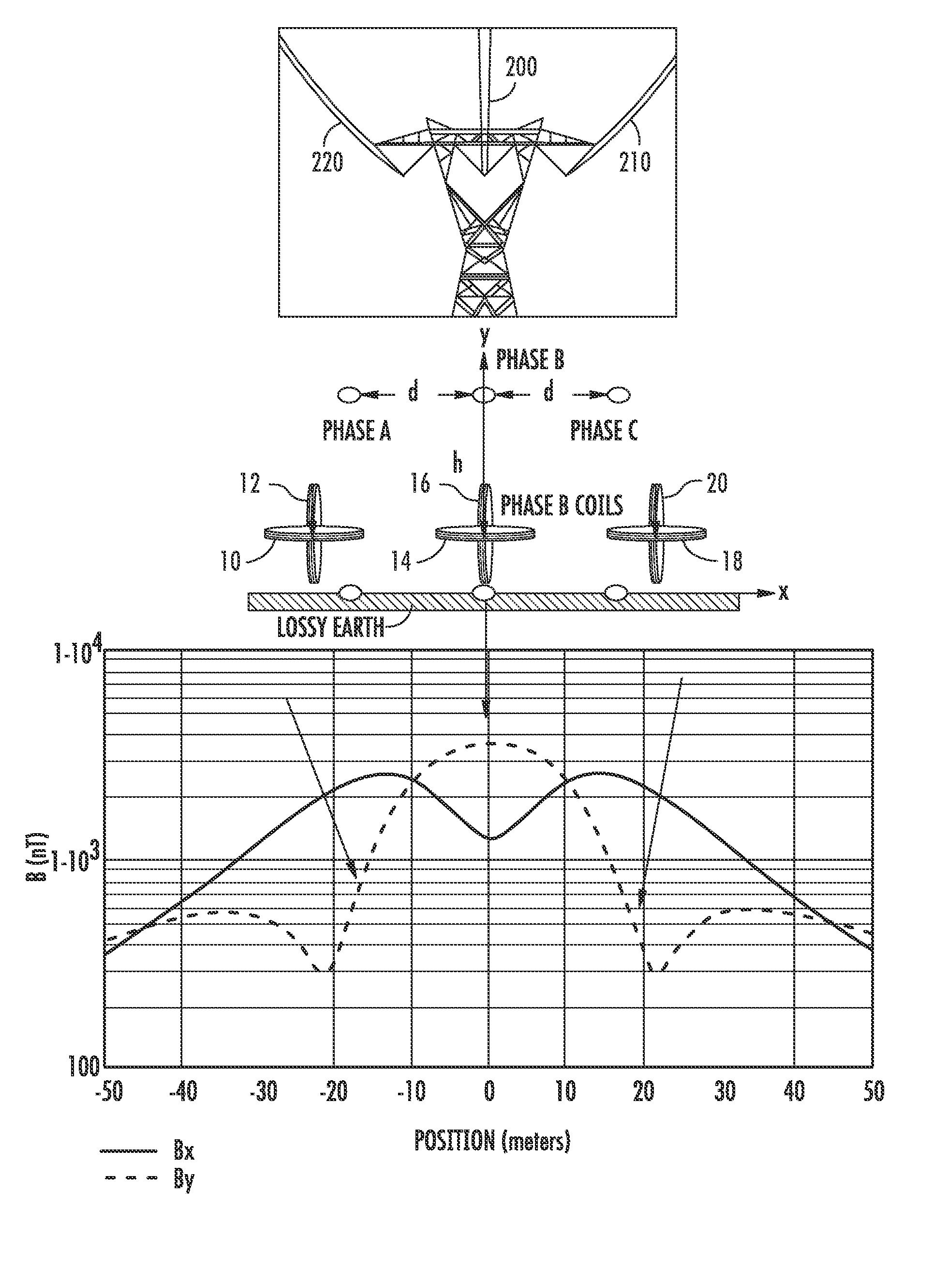
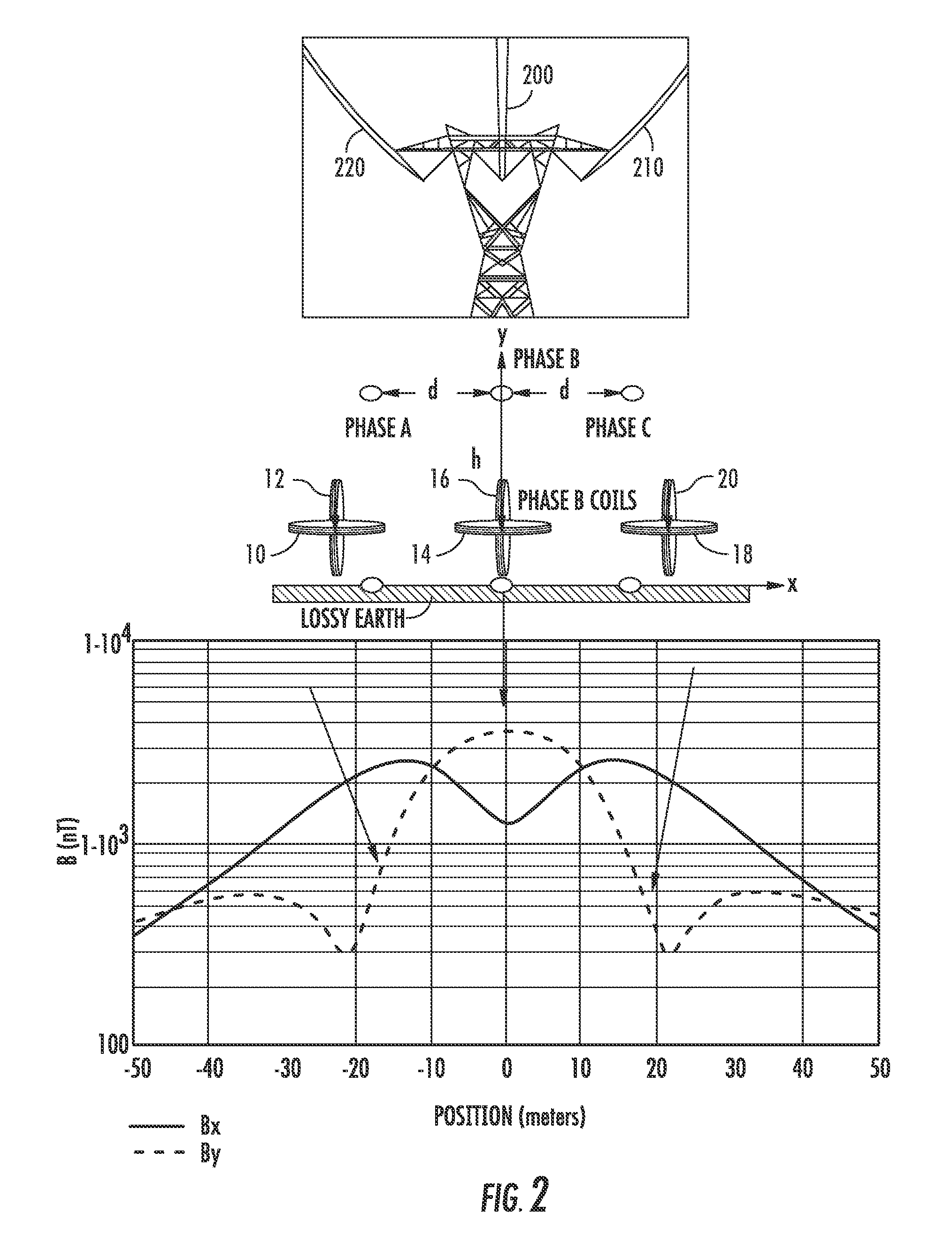
[0028]High voltage overhead phase conductors are very long, gentle catenaries, the electro-mechanical characteristics and behavior of which have been intensely studied are very well understood1. The quasi-lineal phase conductors generate time-varying magnetic fields that, at 60 Hz, may be treated quasi-statically. The field strength at any location can be measured very accurately and, if measured simultaneously at multiple, spatially distinct locations, used to determine accurately the distance to the conductors. The distance, in turn, can be used to determine the sag of the conductors; given this, the average conductor temperature, current phase angle, and magnitude of the current can be accurately established.

[0029]The magnetic field, H, around a phase conductor has magnitude, H=I / 2πr, where r is the distance to the conductor and I is the phase current. In three-phase transmission circuits, the phase currents, I1, I2 and I3, are 120 degrees out of phase, vary widely over the cours...


PUM


Abstract

An apparatus, method, and system for measuring the magnetic field produced by phase conductors in multi-phase power lines. The magnetic field measurements are used to determine the current load on the conductors. The magnetic fields are sensed by coils placed sufficiently proximate the lines to measure the voltage induced in the coils by the field without touching the lines. The x and y components of the magnetic fields are used to calculate the conductor sag, and then the sag data, along with the field strength data, can be used to calculate the current load on the line and the phase of the current. The sag calculations of this invention are independent of line voltage and line current measurements. The system applies a computerized fitter routine to measured and sampled voltages on the coils to accurately determine the values of parameters associated with the overhead phase conductors.

Description

CROSS-REFERENCE TO PRIOR APPLICATIONS[0001]This application is a continuation of and claims the benefit of priority to co-pending International Patent Application No. PCT / US2007 / 077881 filed on Sep. 7, 2007, and published as WO 2008 / 031029. The international case, in turn, claims the benefit of priority to U.S. Provisional Patent Application Ser. No. 60 / 825,093 filed Sep. 8, 2006. The disclosures of both priority cases are hereby incorporated by reference in their entireties.STATEMENT REGARDING FEDERALLY SPONSORED RESEARCH AND DEVELOPMENT[0002]This invention was made with U.S. Government support under Contract No. DE-FG02-05ER84159 awarded by the Department of Energy. The government has certain rights in this invention.FIELD OF THE INVENTION[0003]This invention relates to a reliable, low cost, non-contact, non-invasive, high accuracy, high resolution sensor that will simultaneously monitor high voltage transmission conductor sag, temperature, maximum current-carrying capability (or ...

Claims


Application Information

Patent Timeline
Patent Type & Authority Applications(United States)
IPC IPC(8): G01R21/133G01R21/00
CPCG01R15/142G01R19/2513G01R15/18
Inventor SYRACUSE, STEVEN J.CLARK, ROYHALVERSON, PETER G.TESCHE, FREDERICK M.BARLOW, CHARLES V.
Owner GENSCAPE
Why Eureka
Try Eureka