Mash/lauter tun and method of use thereof

a technology of mash and mash, which is applied in the field of mash/lauter tun and method of use thereof, can solve the problems of high investment of home brewers, high cost, and high cost of separation of wort and mash, and achieve the effect of convenient separation from mash for collection

Active Publication Date: 2009-11-19
BRODERICK WILLIAM
View PDF14 Cites 39 Cited by
  • Summary
  • Abstract
  • Description
  • Claims
  • Application Information

AI Technical Summary

Benefits of technology

[0023]The mash / lauter tun further comprises a method of converting brewing grains to wort. The method of converting brewing grains to wort comprises the steps of obtaining a mash / lauter tun having at least one thermometer extending proximate the center of the mouth / lauter tun and a rotating heat exchanger comprising coils with at least one pressure-operated sparge nozzle. Mash is then heated within the mash / lauter tun by passing fluid through the heat exchanger. The wort is then sparged by increasing pressure in the rotating heat exchanger above a threshold pressure, wherein the sparge nozzle opens at the threshold pressure. Wort is then passed through a double false bottom filter for recovery, while the filter retains the mash grains, rejecting same from the wort. The wort is then transferred from the mash / lauter tun to the wort container. As such, an advantage of the present invention is its ability to streamline the process of transferring the wort from the mash / lauter tun to the wort container.
[0024]More specifically, the present invention is a mash / lauter tun system having a mash / lauter tun, a water heater and a wort container. The wort container comprises, for exemplary purposes only, a brew kettle. The mash / lauter tun comprises a tank for holding mash having a top, a sidewall and a bottom. A lid is disposed on top of the top of the tank and is secured to the tank via lid hold downs. The sidewall of the tank has thermometers disposed therein, and the thermometers extend through to near the center of the tank.
[0025]The heat exchanger comprises gaps surrounding the thermometers. The thermometers are secured to the tank via fasteners. A riser is disposed at the bottom of the tank underneath a base. The mash / lauter tun further comprises a hot water inlet and a wort outlet both disposed on and through the riser. The hot water inlet comprises a hot water valve and the wort outlet comprises a wort outlet valve. The hot water inlet is in fluid communication with the hot water tubing and the flow of water into the hot water inlet is controlled by the hot water valve. Similarly, the wort outlet is in fluid communication with wort transfer tubing, and the flow of wort out of the wort outlet is controlled via the wort outlet valve.
[0026]Additionally, the mash / lauter tun is disposed on a tray of a cart. The cart comprises a base and is supported via legs mounted on the base. The cart is disposed on wheels that facilitate movement of the cart. A water heater and a wort container are disposed on jet cookers on the base of the cart. The jet cookers provide heat sources for heating water in the water heater and brewing the wort in the wort container. The jet cookers are fueled from a gas supply. It will be recognized by those skilled in the art that any known means could provide heat to the wort container without departing from the spirit of the preferred embodiment, such as, for exemplary purposes only, electric heaters.
[0027]The water heater comprises a tank having a front, a back, a top, a bottom, a hot water return inlet and a hot water supply. The hot water return inlet is disposed at the top of the tank and is selectively opened via a hot water return shut off valve. The hot water supply is located at the bottom of the tank and selectively controls the flow of water into the hot water inlet via the hot water inlet valve. The hot water supply provides hot water to a pump via hot water tubing. The water heater is in fluid communication with the pump via the hot water tubing.
[0028]The wort container comprises a tank and a lid. The tank comprises a top and a bottom. The lid of the wort container is disposed over the top of the wort container and also comprises an opening and a handle.

Problems solved by technology

Generally, home brewers invest a great deal time and energy into the process of brewing their own beer.
Secondly, separation of the wort from the mash, often regarded as the most difficult step in the brewing process, comes next, and is initiated when the temperature of the mash is raised to around 170 degrees Fahrenheit.
However, the above systems come with potential drawbacks.
First, the time it takes to raise the mash to the temperature required to transition from the mashing process to the separation process is considerable for both systems.
To decrease this time, the wort would have to be heated to potentially dangerous or damaging temperatures, as even the slightest excessive rise in temperature will essentially scorch and thus ruin the wort.
Secondly, the systems require that the wort constantly be recirculated, which has several disadvantages in and of itself.
Separation of the wort from the mash is often regarded as a highly difficult step due to the delicate nature of the wort and mash, and, as such, adding the wart back to the mash and causing repeated separations can eventually build to several large problems.
If the wart is drained too fast, the mash bed may lack buoyancy and will instead compact against the false-bottom drain, essentially sealing it off.
Also, continuous recirculation of the wart through the mash can lead to uneven heating in the form of stratified heat layers, thereby decreasing the wart quality.
Furthermore, most systems lack the ability to be readily cleaned of residual wort upon the completion of processing.
Thus, sanitation issues can arise if such devices are not thoroughly cleaned.
However, this system potentially suffers from severe uneven heating conditions of the mash, because the mash to the outside of the mash / lauter tun will be heated more rapidly to a higher temperature than the mash in the center of the tun, thus leading ultimately to decreased wort quality.
Also, control of the mash temperature remains through indirect means, making specific, and sometimes very minor, temperature adjustments a difficult and long task.
That is, the tubes are not positioned in such a manner as to lead to maximum heating efficiency of the mash and preclude utilization of thermostats or other measuring instruments from being effectively utilized, since such instruments would be impacted by rotation of the tubes if they extend to the center of the mash.
However, the downfall of such previous devices is that the tubes of the heat exchanger do not extend through a large portion of the mash.
Stirring of the mash by the rotating heat exchanger also leads to grinding of the mash grains against bottom filters, particularly when utilizing the stainless steel filters of many devices, wherein the grinding reduces the size of the grains such that same pass through the filter and remain with recovered wort, thereby contaminating same.

Method used


Image

  • Mash/lauter tun and method of use thereof
  • Mash/lauter tun and method of use thereof
  • Mash/lauter tun and method of use thereof

Examples


Embodiment Construction

[0060]In describing the preferred and selected alternate embodiments of the present invention, as illustrated in FIGS. 1-9, specific terminology is employed for the sake of clarity. The invention, however, is not intended to be limited to the specific terminology so selected, and it is to be understood that each specific element includes all technical equivalents that operate in a similar manner to accomplish similar functions.

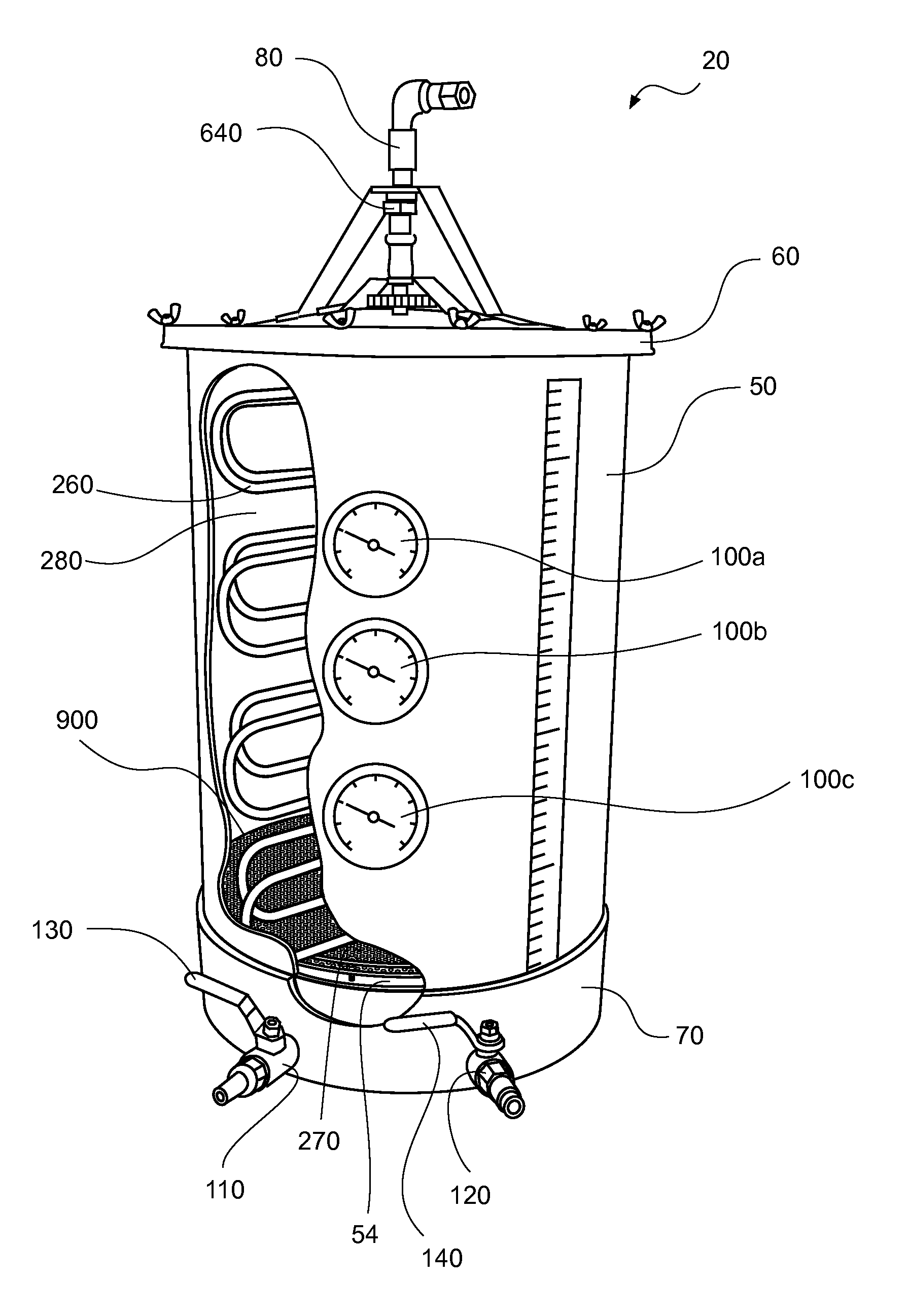
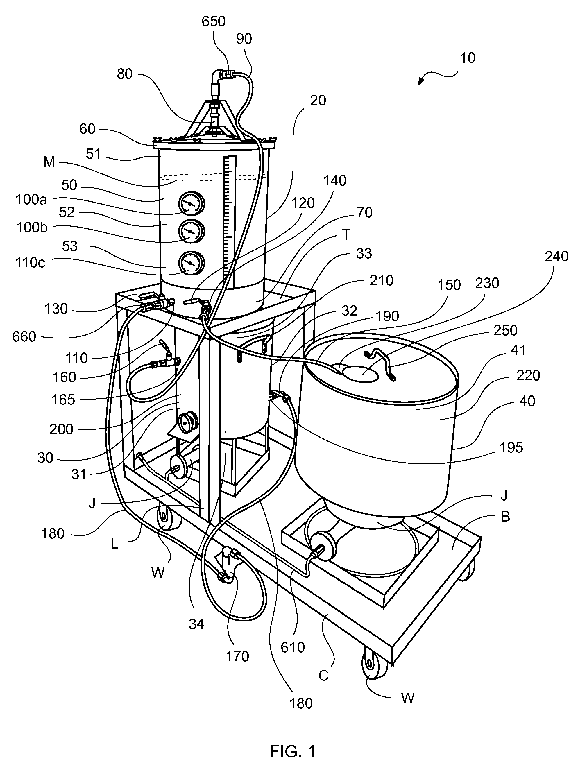
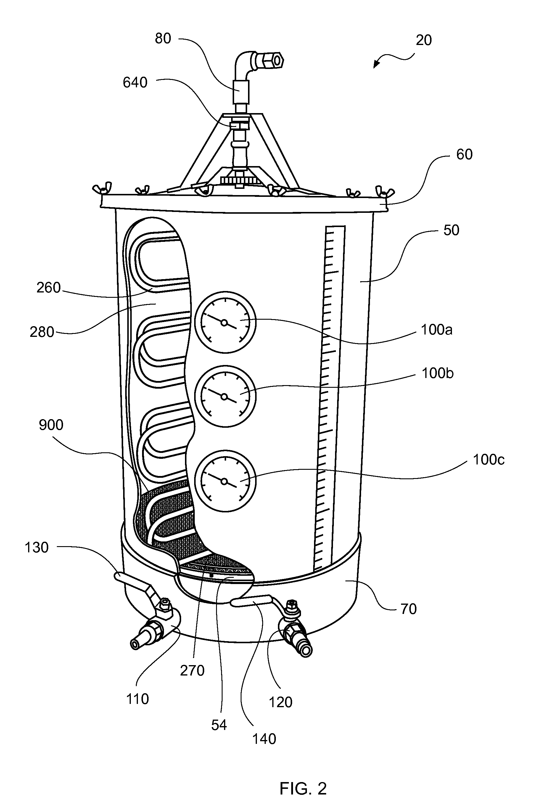
[0061]Brewing comprises several steps in which malted barley is converted to mash, and mash is converted to wort. In order to accomplish this process, malted barley is mixed with warm water and held at a constant temperature, thereby forming mash. Once mash is formed, wort is produced by undergoing mashing and separating. During the mashing process, enzymes cause chemical reactions to break down the complex starches in the barley into simple sugars, thus making wort. As described more fully hereinabove and below, the production of wort takes place in a mash / la...


PUM

PropertyMeasurementUnit
constant temperatureaaaaaaaaaa
temperatureaaaaaaaaaa
pressureaaaaaaaaaa

Abstract

A mash / lauter tun and method of converting grains to wort. The mash / lauter tun comprises a container with a double false bottom filter having two perforated plates disposed parallel with a space therebetween for receiving filtration media. The container further comprises thermometers extending to near the center of the tun and a rotating heat exchanger. In use, mash is loaded into the container and heated via the rotating heat exchanger by passing hot fluid through the rotating heat exchanger. The mash is then sparged by increasing pressure in the rotating heat exchanger above a threshold pressure via closure an outlet valve of the heat exchanger. The wort then passes through the double false bottom filter and is subsequently transferred to a brew kettle for boiling.

Description

CROSS-REFERENCE TO RELATED APPLICATIONS[0001]NoneFEDERALLY SPONSORED RESEARCH OR DEVELOPMENT[0002]NonePARTIES TO A JOINT RESEARCH AGREEMENT[0003]NoneREFERENCE TO A SEQUENCE LISTING[0004]NoneBACKGROUND OF THE INVENTION[0005]1. Technical Field of the Invention[0006]The present invention relates generally to a mash / lauter tun and method of use thereof, and more specifically to a mash / lauter tun comprising a container with a double false bottom filter comprised of two perforated plates disposed parallel with a space therebetween for receiving filtration media. The container further comprises thermometers extending to near the center of the tun and a rotating heat exchanger with sparge nozzles.[0007]2. Description of Related Art[0008]Brewing is a complicated and delicate process, which is described in detail below. It is the production of alcoholic beverages and alcohol fuel through fermentation, whereby sugars get converted into alcohol. The exact process of brewing has generally remain...

Claims


Application Information

Patent Timeline
Patent Type & Authority Applications(United States)
IPC IPC(8): C12C7/04C12M1/02C12C1/033
CPCC12C7/065C12C13/10C12C7/17
Inventor BRODERICK, WILLIAM
Owner BRODERICK WILLIAM
Why Eureka
Try Eureka