Bi-electrode supported solid oxide fuel cells having gas flow plenum channels and methods of making same

a solid oxide fuel cell, bi-electrode technology, applied in the direction of turning machine accessories, final product manufacturing, drawing profiling tools, etc., can solve the problems of affecting the efficiency of the cell, and the inability to meet the requirements of the application. , to achieve the effect of increasing gas flow, increasing thickness, and heat conduction

Inactive Publication Date: 2009-11-19
UNIVERSITY OF TOLEDO +1
View PDF14 Cites 37 Cited by
  • Summary
  • Abstract
  • Description
  • Claims
  • Application Information

AI Technical Summary

Problems solved by technology

Among the major challenges of the ASC technology, various challenges relate to the fabrication and the reliability of the SOFC, particularly in regard to the stacks of cells that make up the SOFC.
In particular, industry is experiencing a number of problems with the ASC design.
1) shrinkage matching of the thick NiO—YSZ cermet anode and the thin YSZ electrolyte during the sintering stage, to temperatures as high as 1550° C.;
2) as the NiO in the anode is reduced to nickel metal there is a volume change that can generate stresses within the anode and cause fracture and failure of the thin YSZ electrolyte;
3) the anode is sensitive to leaks of oxygen which can cause oxidation of the Ni metal to Ni-oxide resulting in a sudden expansion of the anode and failure of the cell;
4) to provide enough strength, the anodes must be made thick, which can lead to diffusion problems in the anode (which works against achieving high fuel utilization rates that are required for commercial applications);
5) the cells are fragile and cannot tolerate the high compressive loading that is required for the compression type seals that are used with the ASC stacking technology (which has required some manufacturers to install additional metal sealing plates), called cassettes, which add to overall complexity and general materials challenges; and,
6) the cathode and electrolyte / anode bi-layers must be fired simultaneously up to 1,250° C. so as to bond the cathode to the electrolyte, a temperature approximately 400° C. higher than the fuel cell's operating temperature, which can result in significant chemical reactivity during fabrication, thus limiting the use of potentially more active and better performing cathode compositions.
However, for higher power demands and for relatively large cells, significantly higher rates of gas flow may be required through the SOFC than can be accommodated through the microchannels alone.

Method used


Image

  • Bi-electrode supported solid oxide fuel cells having gas flow plenum channels and methods of making same
  • Bi-electrode supported solid oxide fuel cells having gas flow plenum channels and methods of making same
  • Bi-electrode supported solid oxide fuel cells having gas flow plenum channels and methods of making same

Examples


example i

Fabrication of Symmetrical Bi-Electrode Supported Cell (Bsc) Structures

[0139]One process of making symmetrical bi-electrode supported solid oxide fuel (BSC) cells can include a high temperature sintering step, which is followed by the process steps of converting each of the electrode scaffolds into active electrodes by imparting catalytic activity to them by solution and thermal treatment means which include separate steps for the anode and the cathode.

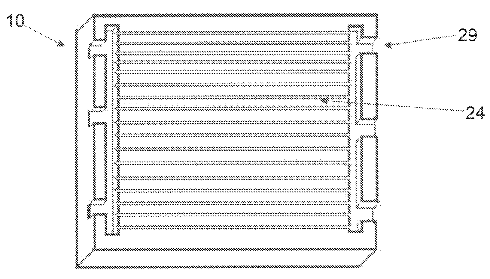
[0140]In certain embodiments, the following method is used to fabricate a single, monolithic, symmetrical, solid-state, bi-electrode supported fuel cell comprising a cathode, an anode and an intervening region of solid electrolyte where at least the electrode includes gas flow plenum channels on one or more outer surfaces.

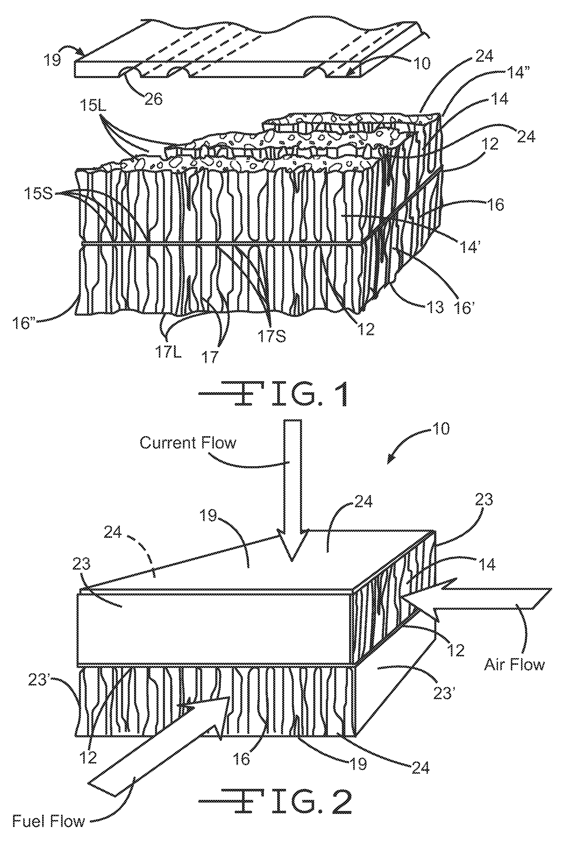
[0141]After forming the electrode scaffolds 14, 16, a thin coating 12′ is applied to the outer surfaces 14a, 16b of the electrodes. It is to be noted that the thin coating 12′ becomes the electrolyte 12 after undergo...

example ii

Formation of Anodes and Cathodes from Electrode Scaffolds

[0157]Subsequent to sintering and cooling of the monolithic bi-electrode supported cell (BSC) structure 10, the respective electrode scaffolds 14, 16 are treated by solution and thermal means to impart anodic and cathodic catalytic properties to the respective electrode scaffolds. In certain embodiments, these methods can include the capillary uptake of metal salt solutions or sols that will become metal or metal oxide catalysts for the operation of the anode and cathode in the completed cell, and thermal treatment, as needed, to cause chemical reduction of catalytically active metals or metal compounds.

[0158]The solution treatment involves the blocking of one electrode scaffold while the other is treated. More specifically, each end of one of the respective electrode scaffolds 14, 16 is masked off to plug the flow microchannels and the gas flow plenum channels 24 with a suitable polymer (for example, such as polypropylene car...

example iii

Forming Gas Flow Plenum Channels

[0166]It is to be understood that there are several fabricating methods that are useful to create the gas flow plenum channels 24, most of which involve creating the gas flow plenum channels while the electrodes 14 and / or 16 are soft and in the “green,” or unfired, state.

[0167]It is also to be understood that the gas flow channels 24 can be formed in both the cathode “air” electrode scaffold 14 and the anode “fuel” electrode scaffold 16; and that in certain other embodiments, the gas flow channels 24 can be formed in only one of the cathode “air” electrode scaffold 14 or the anode “fuel” electrode scaffold 16.

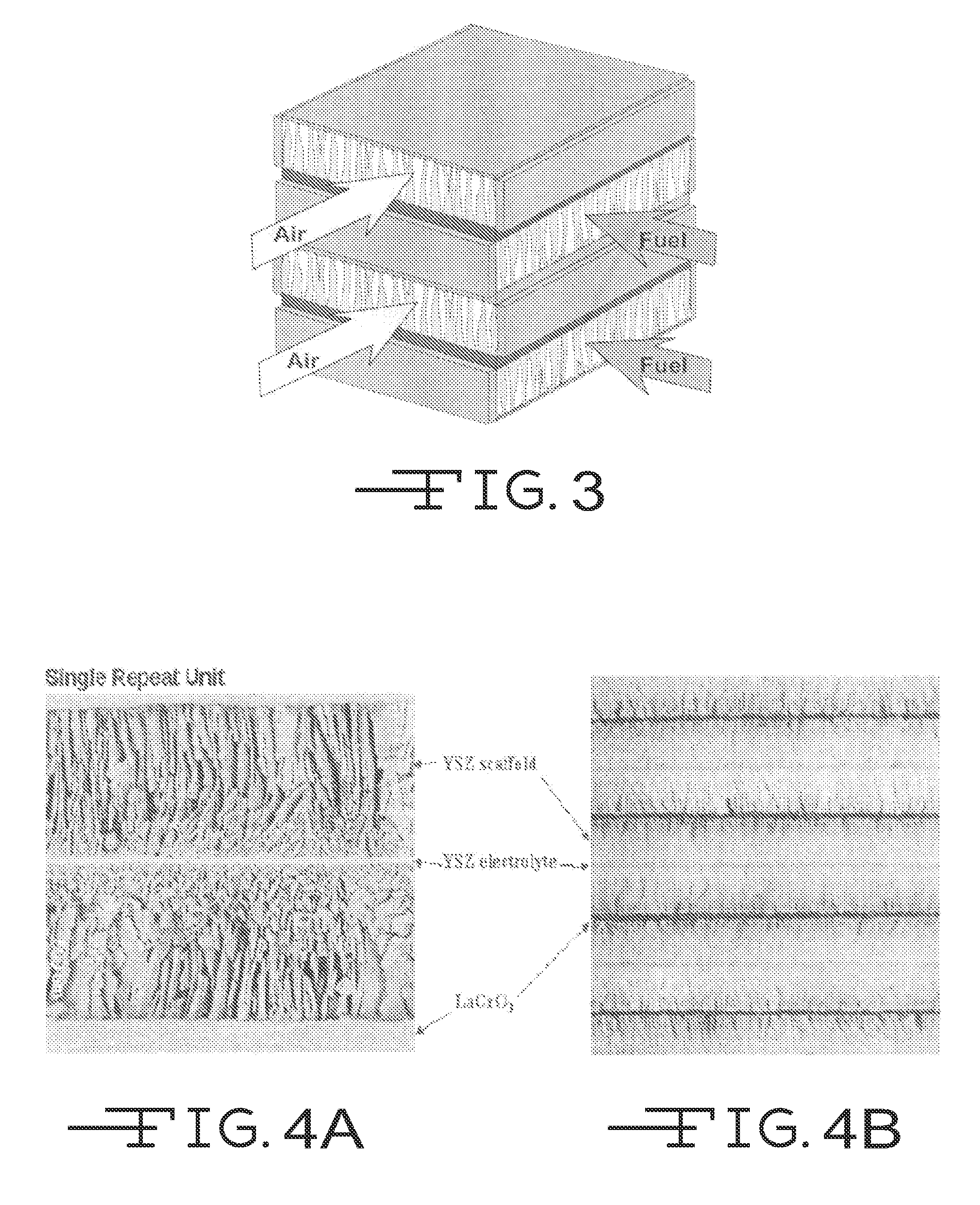
[0168]It is to be understood that the pattern and fabricating methods used to form the gas flow plenum channels 24 can vary, based on the cell design, the intended application, and the stack design. For example, in certain embodiments, the bi-electrode fuel cell (BSC) structure 10 can have a cross-flow design, while, in other embodiments, the bi-...


PUM

PropertyMeasurementUnit
thicknessaaaaaaaaaa
thickaaaaaaaaaa
temperatureaaaaaaaaaa

Abstract

A solid oxide fuel cell (SOFC) has a porous electrode support structure on both sides of a thin electrolyte layer. The porous electrode supported cell is formed with gas flow plenum channels on an outer surface of the electrode scaffold.

Description

CROSS-REFERENCE TO RELATED APPLICATIONS AND STATEMENT REGARDING SPONSORED RESEARCH OR DEVELOPMENT[0001]The present invention claims the benefit of the provisional patent application Ser. No. 61 / 072,833, filed Apr. 3, 2008.[0002]This invention was made with government support under NNC05AA10A. The government has certain rights in this invention.[0003]The invention described herein was made by an employee of the United States Government and may be manufactured and used by or for the Government for Government purposes without the payment of any royalties thereon or therefore.FIELD OF THE INVENTION[0004]The present invention relates generally to fuel cells and high power density solid-oxide fuel cells and solid electrolyzers, and method for the fabrication thereof.BACKGROUND OF THE INVENTION[0005]There is no admission that the background art disclosed in this section legally constitutes prior art.[0006]Fuel cells consist essentially of two electrodes that are in contact with an electrol...

Claims


Application Information

Patent Timeline
Patent Type & Authority Applications(United States)
IPC IPC(8): H01M8/10C04B35/64B29C39/00
CPCC04B35/62655C04B2235/602H01M4/8631H01M4/9033Y02E60/525H01M8/1253H01M8/126Y02E60/521H01M8/1226Y02E60/50Y02P70/50
Inventor SETLOCK, JOHN A.CABLE, THOMAS L.FARMER, SERENE C.
Owner UNIVERSITY OF TOLEDO
Why Eureka
Try Eureka